
C 2500 3/4 Ton Pickup 2WD V8-350 5.7L VIN M 4-bbl (1984)
Depth of cut per side
.005"
.002"
Tool Cross Feed Per Rev.
.006" - .010"
.002" Max.
Vibration Dampener
Yes
Yes
Swirl Pattern - 120 GRIT
No
Optional*
*Duplication of new rotor and smoother finish for best initial brake effectiveness.
When installing new rotor from service stock "do not" refinish the surface as these parts are to recommended finish.
When refinishing brake rotors the following is important:
^
The brake lathe must be in good working order and have capability to produce the intended surface finish.
^
Use correct tool feed and arbor speeds. Too fast a speed or too deep a cut can result in a rough finish.
^
Cutting tools must be sharp.
^
Adapters must be dean and free of nicks.
^
Lathe finish cuts should be further improved and made nondirectional by dressing rotor surface with a sanding disc power tool (AMMCO
Model 8350 Safe Swirl Disc Rotor Grinder or equivalent).
^
Rotor surfaces are to be refinished to 20 to 60 micro-inch.
To become familiar with the required surface finish, drag a fingernail over the surface of a new rotor from parts stock or one on a new vehicle. If
your brake equipment cannot produce this smooth a finish when correctly used, contact the equipment manufacturer for corrective instructions.
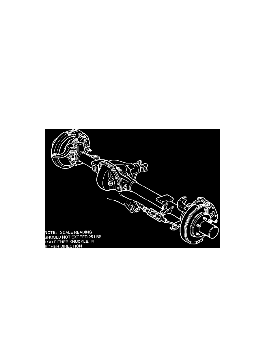
Checking Ball Joint Turning Effort (K-V10, K-V20)
FIGURE NO. 3 - Ball Joint Turning Effort
Front axle ball joint adjustment is generally necessary only when there is excessive play in steering, irregular wear on tires or persistent loosening of the
tie rod is observed.
1.
Raise vehicle on hoist then place jack stands just inside of front springs.
2.
Disconnect connecting rod and tie rod to allow independent movement of each steering knuckle.
3.
Apply a fish-scale to the tie rod mounting hole of the steering knuckle arm. With the knuckle assembly in the straight-ahead position, determine
the right angle pull required to keep the knuckle assembly turning after initial break-away. This pull should not exceed 25 lbs for each knuckle
assembly in either direction.
4.
If the turning effort exceeds 25 lbs. in either direction, adjustment or replacement will be necessary. Follow the procedure in Section 3C of the
1988 Light Duty Service Manual X-8832.
Technical Service Bulletin # 883795
Date: 881201