
C 2500 Suburban 2WD V8-454 7.4L (1994)
Oxygen Sensor: Description and Operation
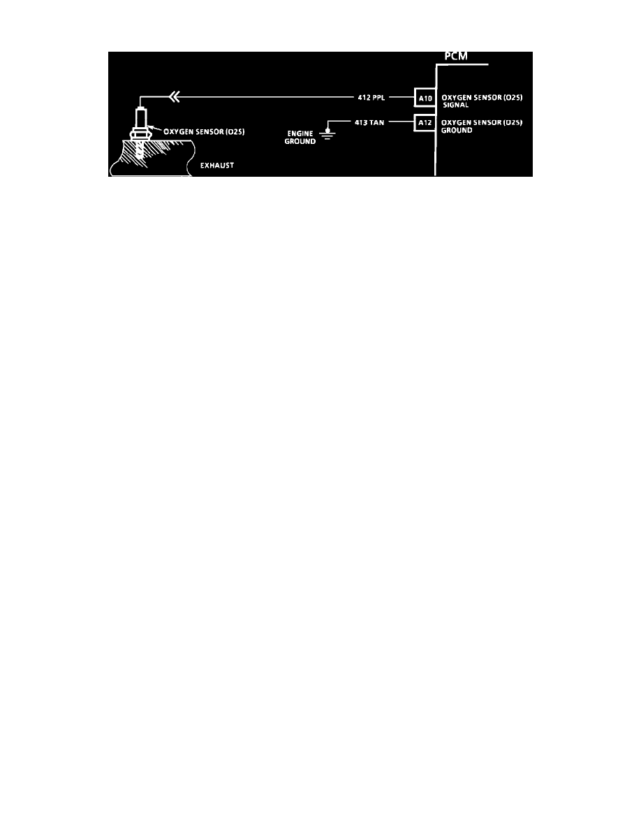
Oxygen Sensor Circuit Wiring Diagram
PURPOSE:
The Oxygen sensor (O2 Sensor) has the ability to produce a low voltage signal that feeds information on engine exhaust content to the control
module.
The oxygen sensor is located in the exhaust system. The sensor monitors atmospheric air versus exhaust gas oxygen content to produce a voltage
output. This voltage ranges from approximately 0.1 volt (high oxygen - lean mixture) to 0.9 volt (low oxygen - rich mixture). By monitoring the
oxygen sensor output voltage, the computer can determine the amount of oxygen in the exhaust gas and adjust the air/fuel mixture accordingly.
CONSTRUCTION:
The O2 Sensor is constructed from a zirconia/platinum electrolytic element. Zirconia is an electrolyte that conducts electricity under certain
chemical conditions. The element is made of a ceramic material and is an insulator when cold. At operating temperature, 315~C (600~F), the
element becomes a semiconductor. A platinum coating on the outer surface of the element stimulates further combustion of the exhaust gases right
at the surface and this helps deep the element up to the desired temperature. The O2 Sensor has an inter cavity which is filled with atmospheric
(reference) air. The atmosphere has approximately 21% oxygen in it. In the electrical circuit this inter cavity is the positive (+) terminal. The outer
surface of the element is exposed to the exhaust gas stream. It is the negative (-) terminal.
Due to the electrolytic properties of the element the oxygen concentration differences between the reference air and the exhaust gases produce
small voltages.
OPERATION:
A rich exhaust (excessive fuel) has almost no oxygen. When there is a large difference in the amount of oxygen touching the inside and outside
surfaces, there is more conduction, and the sensor puts out a voltage signal above 0.6 volts (600 mV). With lean exhaust (excessive oxygen) there
is about two percent oxygen in the exhaust. This is a smaller difference in oxygen from the outside surfaces which results in less conduction and a
voltage signal below 0.3 volts (300 mV). The voltages are monitored and used by the control module to "fine tune" the air/fuel ratio to achieve the
ideal mixture desired.
The control module puts out a reference signal of 0.45 volts (450 mV). The reference signal serves two purposes. The first is to run the engine
when it is in OPEN LOOP mode of operation. When the air/fuel ratio is correct the control module senses 450 mV. When the engine is operating
with a rich air/fuel ratio there is a reduction of free oxygen in the exhaust stream and the O2 sensor voltage rises above the reference voltage.
When the engine is running lean the voltage drops below the reference voltage due to the excess oxygen in the exhaust stream. The O2 sensor
provides the feedback information for the CLOSED LOOP operating mode of the fuel delivery system. The O2 sensor indicates to the control
module what is happening in the exhaust. It does not cause things to happen. It is a type of gauge: Low voltage output = lean mixture = high
oxygen content in the exhaust; high voltage output = rich mixture = low oxygen content in the exhaust.
CONDITIONS THAT CAN SET CODES:
An open O2 sensor, should set a Diagnostic Trouble Code (DTC) 13. A constant low voltage in the O2 sensor circuit should set a DTC 44. A
constant high voltage in the circuit should set a DTC 45. DTC 44 and DTC 45 could be set as a result of fuel system problems.