
C 2500 Suburban 2WD V8-454 7.4L (1994)
OBD Circuit
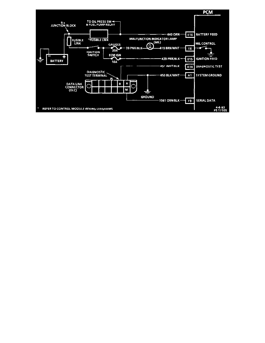
Circuit Description:
The on-board diagnostic system check is an organized approach to identifying a problem created by a control module system malfunction. It must be the
starting point for any driveability complaint diagnosis, because it directs the service technician to the next logical step in diagnosing the complaint.
Understanding the chart and using it correctly will reduce diagnostic time and prevent the unnecessary replacement of good parts.
Chart Test Description: Number(s) below refer to circled number(s) on the diagnostic chart.
1. This step is a check for the proper operation of the MIL (Service Engine Soon). The MIL should be "ON" steady.
2. Use Tech 1 to aid diagnosis, therefore, serial data must be available. If a PROM (MEM-CAL) error is present, the PCM may have been able to
flash DTC 12/51, but not enable serial data.
3. Although the PCM is powered up, a "Cranks But Will Not Run" symptom could exist because of a PCM or system problem.
4. This step will isolate if the customer complaint is a MIL or a driveability problem with no MIL. Refer to "TROUBLE CODE DESCRIPTION"
See: Testing and Inspection/Diagnostic Trouble Code Descriptions in this section for a list of valid DTCs. An invalid DTC may be the result of a
faulty scan tool, PROM (MEM-CAL) or PCM.
5. Comparison of actual control system data with the Typical Tech 1 Data Values is a quick check to determine if any parameter is not within limits.
Keep in mind that a base engine problem (i.e., advanced cam timing) may substantially alter sensor values.