
C 2500 Suburban 2WD V8-454 7.4L (1994)
D. Wiring protectors (33) and (34).
E. Gently pull wire harness through column.
13. Key from steering column lock cylinder set (17).
14. Buzzer switch assembly (13).
15. Insert key in lock cylinder (17).
^
Key in "lock" position.
16. Lock retaining screw (14).
Removing Components From Upper Shaft
17. Steering column lock cylinder set (17).
INSTALL OR CONNECT
NOTICE: Ensure all fasteners are securely seated before applying needed torque. Failure to do may result in component damage or malfunctioning of
steering column.
1. Steering column lock cylinder set (17).
2. Lock retaining screw (14).
TIGHTEN
^
Tighten screw (14) to 4.5 Nm (40 lb.in.).
3. Key from lock cylinder set (17).
4. Buzzer switch assembly (13).
5. Reinsert key in lock cylinder set (17).
^
Key in "lock" position.
6. Turn signal switch assembly (10) wire harness through steering column.
A. Let switch hang freely.
B. Switch connector to vehicle wire harness.
C. Wiring protectors (33) and (34).
D. Support bracket (52).
E. Hex head bolts (53).
TIGHTEN
^
Tighten bolts (53) to 30.0 Nm (22 lb.ft.).
7. Turn signal switch (10) and three screws (7).
TIGHTEN
^
Tighten screws (7) to 3.4 Nm (30 lb.in.).
8. Switch actuator arm (9) and screw (8).
TIGHTEN
^
Tighten screw (8) to 2.3 Nm (20 lb.in.).
9. Hazard knob assembly and multi-function lever.
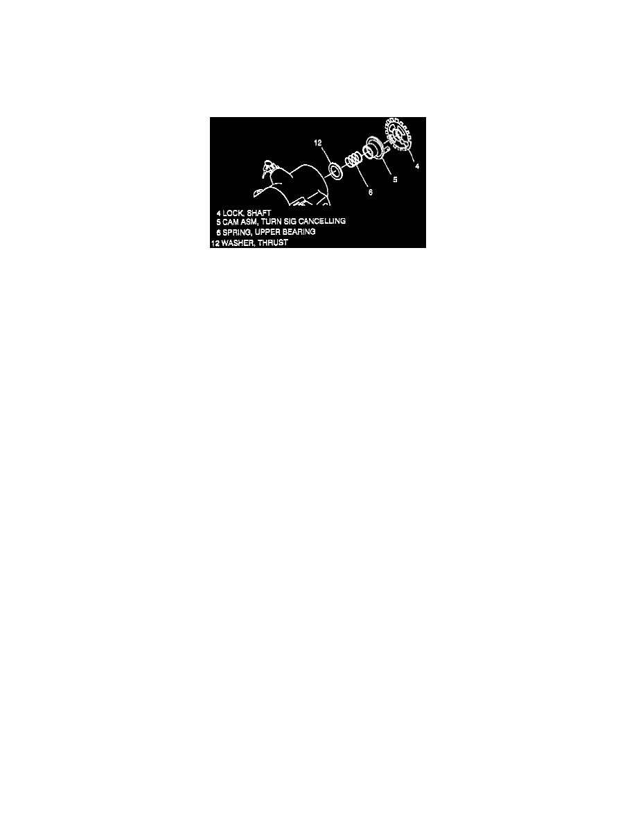
10. Thrust washer (12).
11. Upper bearing spring (6).
12. Turn signal cancelling cam assembly (5). Lubricate with grease, synthetic (service kit).
13. Shaft lock (4).
14. New shaft lock retaining ring (3) using J 23653-C to push down shaft lock (4).