
C 2500 Suburban 2WD V8-5.7L VIN R (1996)
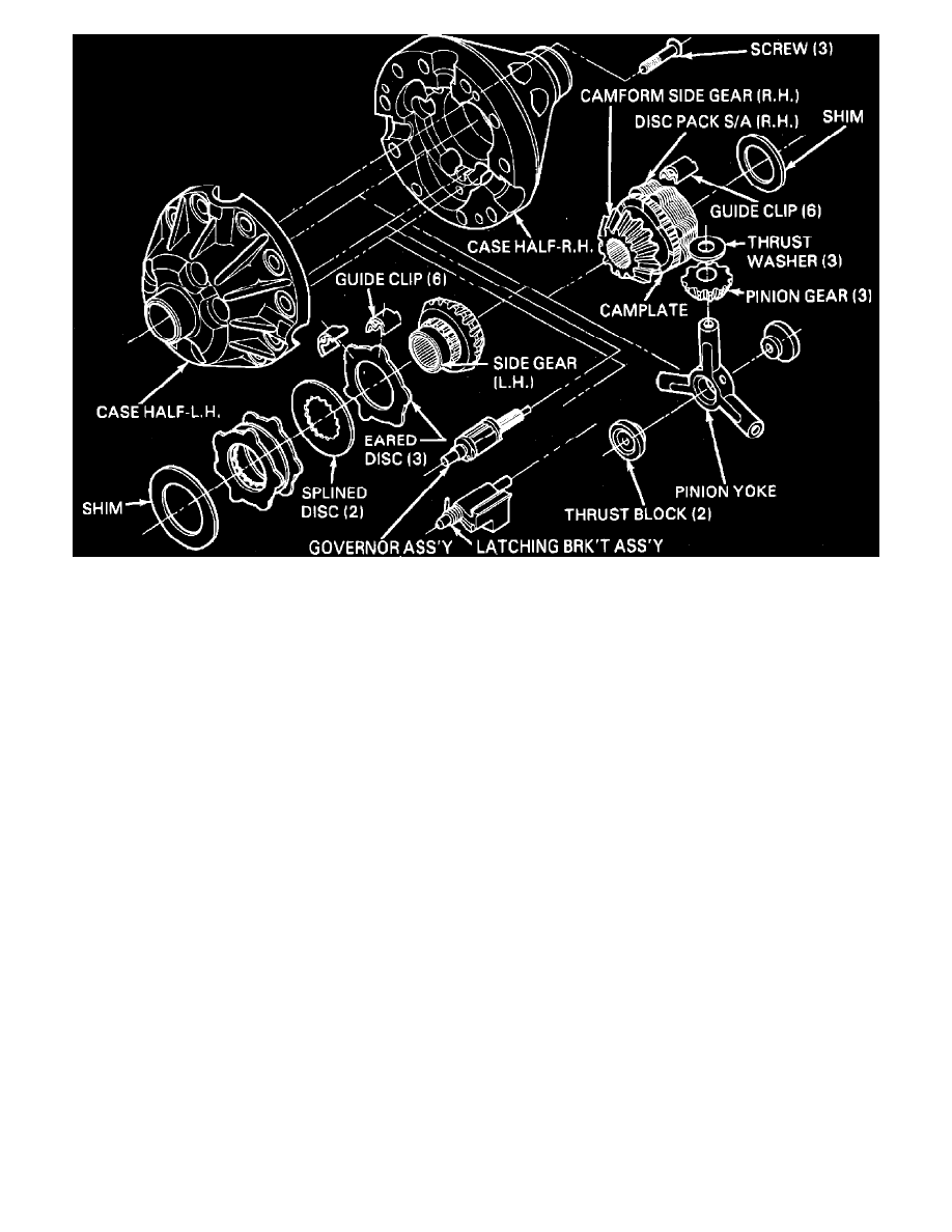
Fig. 2 Eaton locking differential exploded view
7.
Install governor and latching bracket in respective positions,
Fig. 2, and position straight end of latching bracket spring over and to the outside of
governor shaft to preload bracket against governor.
8.
Install 6 guide clips on ears of side gear disc pack using grease to retain clips.
9.
Install selected shim in left case half.
10.
Carefully remove disc pack from side gear and lower assembly into right case half, ensuring that guide clips are properly positioned.
11.
Insert side gear through disc pack into left case half, rotating gear as needed to align splines.
12.
Hold side gear into case, then lower left case assembly onto right case half, ensuring that bores for governor and latching bracket shafts are
properly aligned.
13.
Invert assembly taking care not to dislodge internal components, then install 3 retaining screws.
14.
Mount axle shaft in vise with spline protruding enough to engage side gear.
15.
Install case assembly over axle shaft and rotate case to check operation. Assembly should rotate smoothly, without binding or locking-up.
16.
Install ring gear and side bearings as outlined for standard differential. Refer to
Corporate - Standard. See: 10 1/2 Inch Ring
Gear/Overhaul/Corporate - Standard
Axle Disassembly
1.
Drain lubricant from axle housing and remove axle shafts.
2.
Disconnect propeller shaft from companion flange, tape bearing caps to universal joint spider and secure shaft aside.
3.
Remove bolts securing carrier to axle housing and the lockwashers, support carrier and remove carrier assembly from axle housing.
4.
Mount carrier assembly in suitable holding fixture.
5.
Loosen ring gear thrust pad locknut and remove thrust pad.
6.
Remove side bearing adjuster locks, bearing cap bolts and lock washers.
7.
Mark position of bearing caps for assembly, then remove bearing caps by tapping cap bosses with soft faced hammer.
Do not pry caps from
carrier as they may be damaged. Keep all components in order to aid assembly.
8.
Remove differential case assembly from case, along with side bearing outer races, and place races with respective bearing caps.
9.
Remove bolts securing pinion bearing housing to carrier, then separate pinion housing from carrier by tapping with soft faced hammer.
10.
Inspect components as outlined and replace as needed.
Keep all components in order so that any component to be reused can be installed in
original position.
Differential Service
DIFFERENTIAL, DISASSEMBLE