
C 2500 Truck 2WD V8-454 7.4L VIN J SFI (1996)
Air Injection Pump: Description and Operation
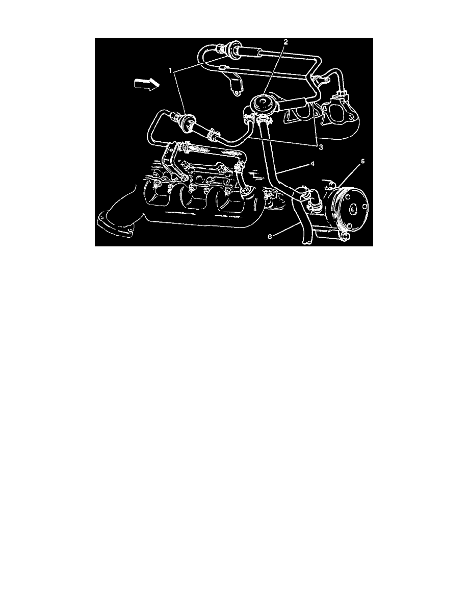
Diagram
Function
The Secondary Air Injection (AIR) system is used to reduce Carbon Monoxide (CO) and Hydrocarbons (HC).
The AIR system add air (oxygen) to the exhaust manifold to continue oxidation after the exhaust gasses have left the combustion chamber. The heat from
this reaction brings the catalytic converter up to operating temperature faster when the engine is cold.
This system consists of an AIR pump, VCM controlled electronic clutch, check valves, and necessary plumbing. A belt driven AIR pump supplies
filtered air from the air intake system to the AIR injection pipes. The check valves, on the AIR injection pipes, prevent backflow of exhaust gasses in the
AIR pump.
When the engine is started with a coolant temperature above approximately 15°C (45°F) or if the fuel system is in the Decel Mode, the VCM energizes
the AIR relay. The AIR relay then energizes the AIR clutch, which directs air into the exhaust manifold ports.
The control module may turn the AIR pump OFF when any of the following conditions occur:
^
The system is in the Closed Loop mode.
^
Any Diagnostic Trouble Code (DTC)s are set.
^
The system is in Power Enrichment mode for more than a short period of time.
^
Low manifold pressure (over run) Quick vacuum rise (rapid decel).
Legend
(1) AIR Check Valve
(2) AIR Valve
(3) AIR Pump Crossover Pipe
(4) AIR Pump Output Hose
(5) AIR Pump
(6) AIR Pump Air Cleaner Hose