
C 3500 Truck 2WD V8-454 7.4L VIN J SFI (1999)
Vehicle Control Module: Description and Operation
Vehicle Control Module
General Description
The vehicle control module (VCM) is located in the engine compartment. The VCM is the control center for the engine component systems which effect
engine operation. The VCM constantly monitors and processes information from the various information sensors and switches. The VCM then sends the
necessary electrical responses to control the various control system components. Review the wiring diagrams in order to determine which systems are
controlled by the VCM. The VCM has the ability to perform on-board diagnostic tests on itself, the information system components, and certain control
system components. The VCM has the ability to alert the driver of a malfunction by illuminating a malfunction indicator lamp (MIL). The VCM has the
ability to store certain information pertaining to a malfunction, including Diagnostic Trouble Codes (DTC)s. Using serial data communication, a scan
tool can retrieve this information in order to be viewed by the technician. The technician can use this information in order to identify, diagnose, and
verify the repair of the malfunction. The VCM is sometimes referred to as the control module.
Memory
The VCM control calibrations for a particular vehicle are based on the Vehicle Identification Number (VIN). The calibrations are stored in the
Electrically Erasable Programmable Read-Only Memory (EEPROM). The EEPROM is part of the VCM and can not be replaced. The EEPROM can be
reprogrammed using the Techline equipment. The electronic ignition control module is located in the VCM. The knock sensor module contains the
Knock Sensor (KS) system calibrations. The knock sensor module is not part of the VCM and is serviced separately from the VCM. The VCM has the
ability to make corrections in the fuel control system to allow for minor vehicle variations.
This information is stored in the random access memory (RAM). RAM needs a constant voltage supply to be retained. The short term fuel trim and the
long term fuel trim are stored in RAM. When the battery is disconnected during service of the vehicle this memory is lost and the driver may notice a
change in the performance of the vehicle. In order to restore this memory perform the following steps:
1. Start the engine.
2. Allow the engine to reach normal operating temperature.
3. Drive the vehicle under idle, partial throttle, and moderate acceleration conditions.
4. Continue until normal vehicle performance returns.
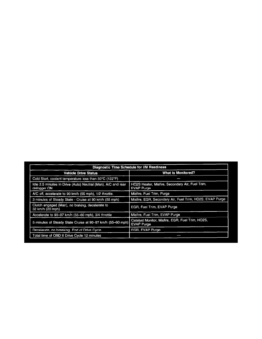
System Status and Drive Cycle For Inspection/Maintenance (I/M)
Typical OBD II Drive Cycle
Some areas require that certain vehicles run and pass on-board diagnostic test of particular emissions systems.
Using a scan tool, the technician has the ability to monitor the System Status of the following systems:
^
The catalyst monitoring system
^
The evaporative (EVAP) system
^
The heated oxygen sensor (HO2S)
^
The heated oxygen sensor (HO2S) heater
^
The exhaust gas recirculation (EGR) system
^
The air injection reaction (AIR) system (if so equipped).
IMPORTANT: The System Status display indicates whether or not a diagnostic test is completed. Diagnose and repair the system if any of the
on-board diagnostic tests has failed the last test. Verify that all of the required diagnostic tests pass prior to returning the vehicle to the customer. Use the
Typical Drive Cycle table as a guide to complete the System Status test associated with I/M.