
C 3500 Truck 2WD V8-454 7.4L VIN J SFI (1999)
RH Horn A Note
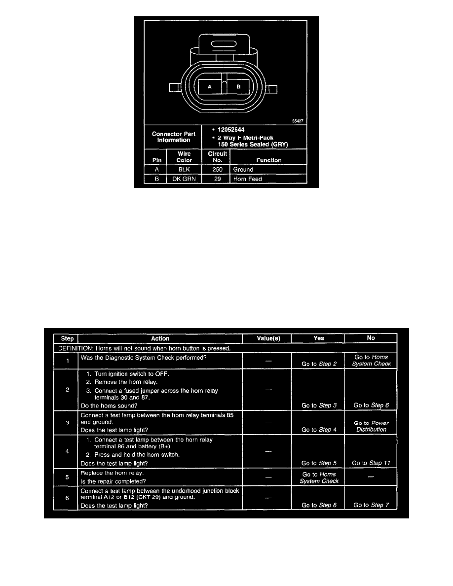
Connector end views show the cavity or terminal locations for all the related 2-pin or larger connectors shown in the system schematic(s). The drawings
show the connector's face as seen after the harness connector has been disconnected from a component or mating connector. Unused cavities are left
blank in the table.
In addition, the color and part number of the connector body is provided along with the family/series name. Below is an example of a typical connector
end view.
Diagnostic System Checks
IMPORTANT: Misdiagnosis could occur if the diagnostic system check is not performed before using the diagnostic tables.
The diagnostic system check determines the diagnostic trouble codes (DTCs) present, verifies proper communication, and navigates to the appropriate
diagnostic table.
Diagnostic Tables
Horns Inoperative (Part 1 Of 2)