
C 3500 Truck 2WD V8-6.6L DSL Turbo VIN 1 (2002)
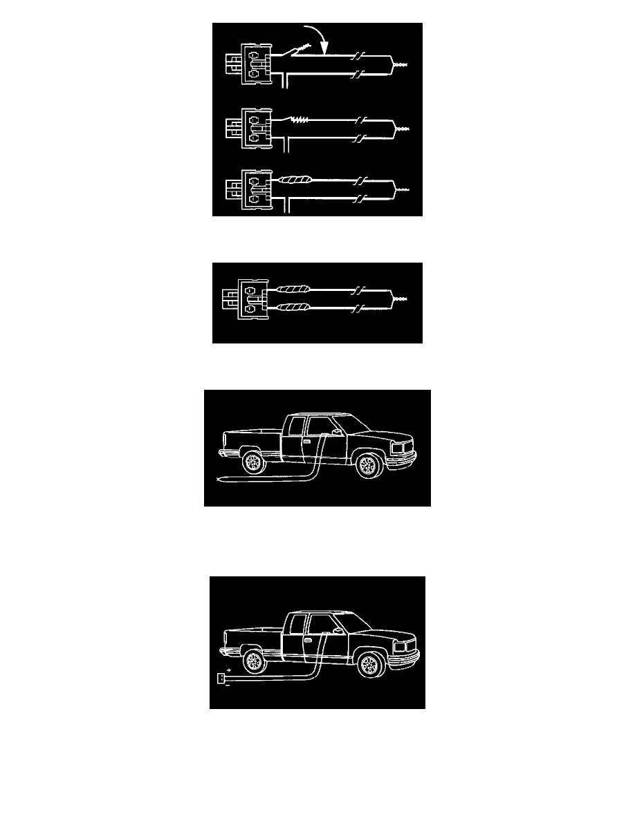
25. Bend flat the twisted connection.
26. Secure and insulate the connection using electrical tape.7
27. Twist together, bend and tape the remaining connector wire lead to the remaining deployment wire.
28. Connect the deployment harness to the IP module connector.
29. Route the deployment harness out of the vehicle's passenger side.
30. Stretch the driver side harnesses to full length.
31. Stretch the passenger side harnesses to full length.
32. Completely cover the windshield and front door window openings with a drop cloth.
33. Place a power source, 12 V minimum/2 A minimum, i.e., a vehicle battery, near the shorted ends of the passenger side deployment hamesses.
34. Separate the 2 ends of the IP module deployment harness wires.
35. Connect the IP module deployment harness wires to the power source in order to deploy the IP module.
36. Disconnect the P module deployment harness wires from the power source.