
C 3500 Truck 2WD V8-6.6L DSL Turbo VIN 1 (2002)
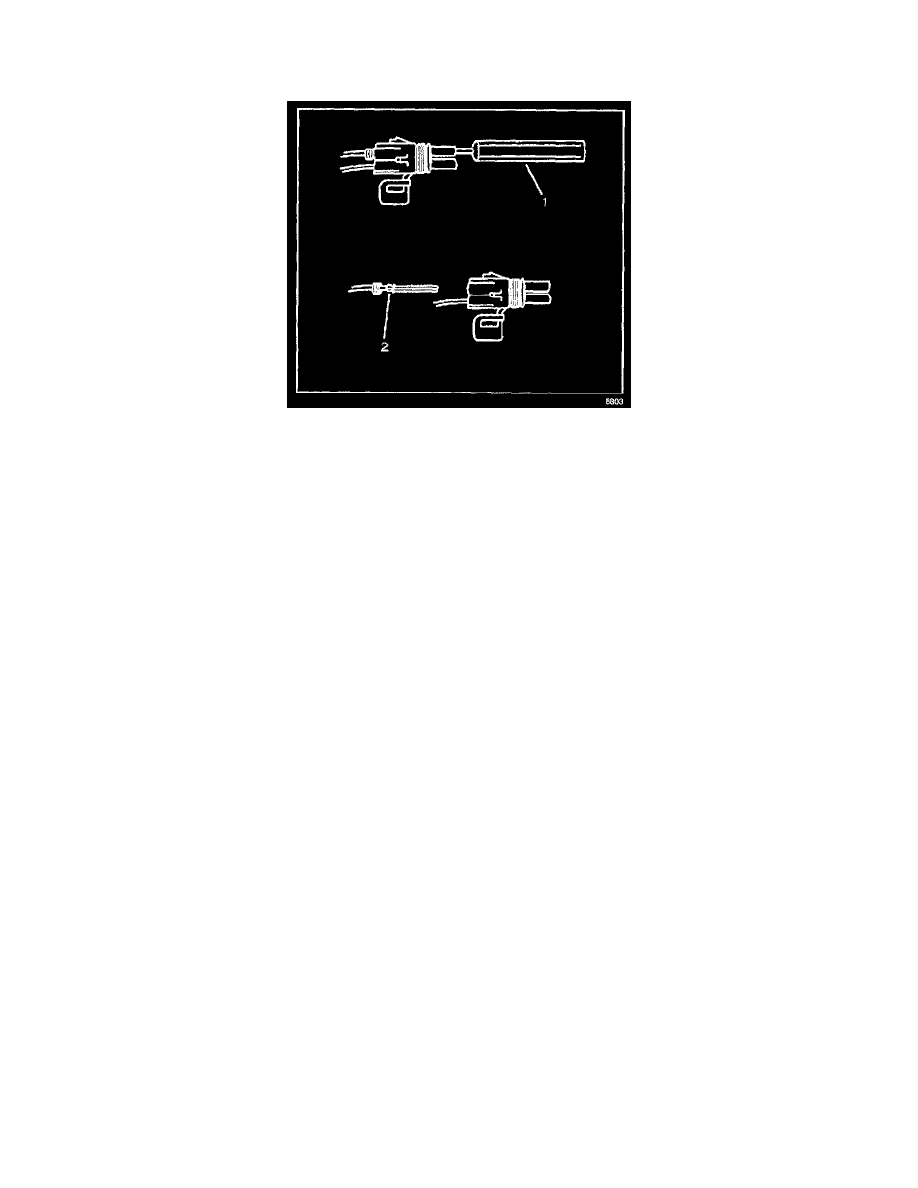
1. Separate the connector halves (1).
2. Open the secondary lock. A secondary lock aids in terminal retention and is usually molded to the connector (1).
3. Grasp the wire and push the terminal to the forward most position. Hold the wire in this position.
4. Insert the Weather Pack(R) terminal removal tool into the front (mating end) of the connector cavity until it rests on the cavity shoulder (1).
5. Gently pull on the wire to remove the terminal through the back of the connector (2).
IMPORTANT: Never use force to remove a terminal from a connector.
6. Inspect the terminal and connector for damage. Repair as necessary. Refer to Repairing Connector Terminals. See: General Electrical Diagnostic
Procedures/Wiring Repairs/Connector Repairs/Repairing Connector Terminals
7. Reform the lock tang (2) and reset terminal in connector body.
8. Close secondary locks and join connector halves.
9. Verify that circuit is complete and working satisfactorily.
10. Perform system check.
General Information
The Wiring Repairs contains the following types of wiring repair information. Using these elements together will make wiring repair faster and easier:
-
Circuit Protection-Fuses
-
Circuit Protection-Circuit Breakers
-
Circuit Protection-Fusible Links
-
Repairing Damaged Wire Insulation
-
Splicing Copper Wire Using Splice Clips
-
Splicing Copper Wire Using Splice Sleeves
-
Splicing Twisted or Shielded Cable
-
Splicing Inline Harness Diodes
-
Heated Oxygen Sensor (HO2S) Wiring Repairs
-
SIR/SRS Wiring Repairs
-
Flat Wire Repairs
Repairing Damaged Wire Insulation
If the conductive portion of the wire is not damaged, locate the problem and apply tape around the wire. If the damage is more extensive, replace the
faulty segment of the wire. Refer to Splicing Copper Wire Using Splice Clips and follow the instruction to repair the wire. See: General Electrical
Diagnostic Procedures/Wiring Repairs/Typical Electrical Repairs/Splicing Copper Wire Using Splice Clips
SIR/SRS Connector (Plastic Body and Terminal Metal Pin) Repair
Use the connector repair assembly packs in order to repair the damaged SIR/SRS wire harness connectors and the terminals. Do not use the connector
repair assembly pack in order to repair the pigtails. These kits include an instruction sheet and the sealed splices. Use the sealed splices in order to splice
the new wires, connectors, and terminals to the harness. The splice crimping tool is color keyed in order to match the splices from the J 38125-B. You
must use the splice crimping tool in order to apply these splices.
The terminals in the SIR/SRS system are made of a special metal. This metal provides the necessary contact integrity for the sensitive, low energy
circuits. These terminals are only available in the connector repair assembly packs. Do not substitute any other terminals for those in the assembly packs.
If the individual terminals are damaged on the sensing and diagnostic module (SDM) harness connector, use 1 of the following 2 components in order to
replace the SDM harness connector:
-
The SDM harness connector pigtail assembly
-
The SDM harness connector replacement kit