
C 3500 Truck 2WD V8-8.1L VIN G (2001)
-
Tighten the coupler clamp bolt to 45 Nm (33 ft. lbs.).
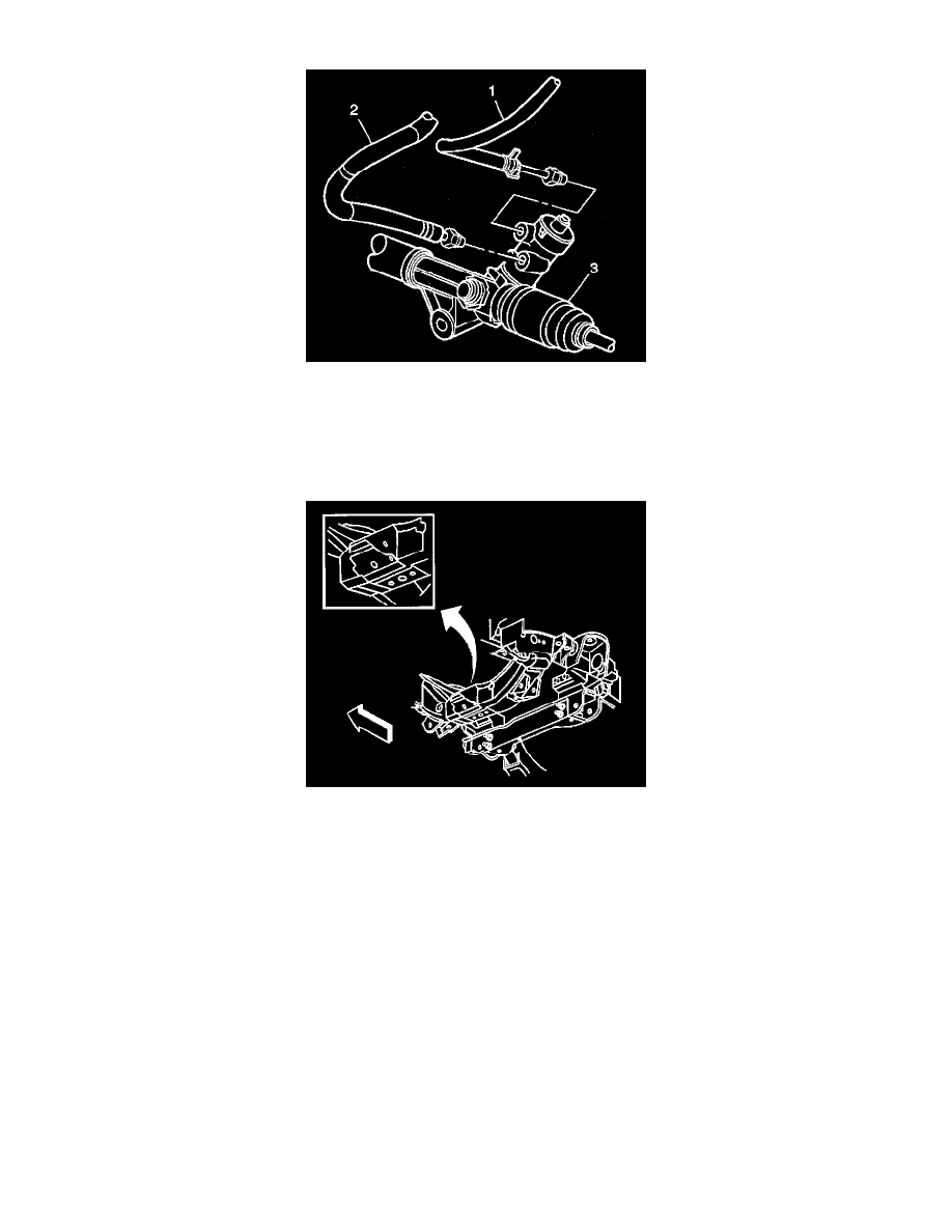
5. Install the power steering low pressure hose (1) to the rack and pinion assembly (3).
6. Install the power steering high pressure hose (2) to the rack and pinion assembly (3).
-
Tighten the hoses to 27 Nm (28 ft. lbs.).
7. Install the engine protection shield, if equipped. Refer to Engine Protection Shield Replacement in Body and Frame.
8. Install the outer tie rod end to the steering knuckle. Refer to Tie Rod End Replacement- Outer.
9. Install the stabilizer shaft. Refer to Stabilizer Shaft Replacement.
10. If the steering gear is equipped with a ground strap, install the ground strap to the crossmember bracket.
-
Place the ground strap on the left side of the bracket and mark the location.
-
Center punch the bolt hole location.
-
Drill a hole using a 7 mm (9/32 inch) drill bit.
-
Install the bolt and washer retaining the ground strap to the crossmember.
-
Tighten the ground strap retaining bolt to 10 Nm (89 inch lbs.).
11. Install both of the front tire and wheel assemblies. Refer to Tire and Wheel Removal and Installation.
12. Remove the safety stands.
13. Lower the vehicle.
14. Bleed the power steering system. Refer to Bleeding the Power Steering System.
Worm Thrust Bearing Preload Adjustment
-
Tools Required
-
J 42882 Adjuster Nut Socket
-
J 43435 Adjuster Lock Nut Wrench