
Canyon 2WD L5-3.5L VIN 6 (2004)
^
M6 X 1.0 X 54.4 (2)
^
M6 X 1.0 X 47.5 (3)
^
M6 X 1.0 X 17.7 (4)
^
M6 X 1.0 X 35.0 (5)
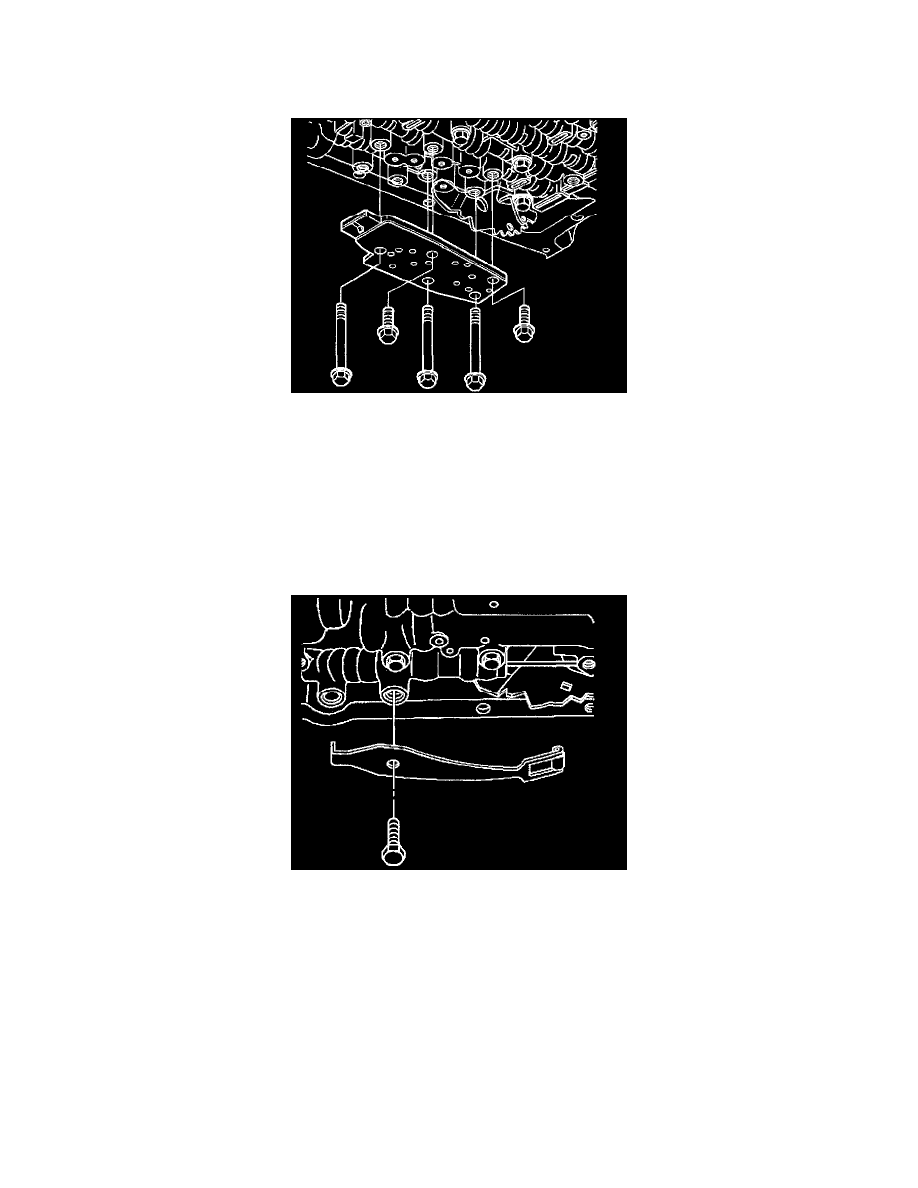
6. Install the TFP manual valve position switch.
7. Install but do not tighten the control valve body bolts securing the TFP manual valve position switch to the control valve body.
Notice: Refer to Fastener Notice in Service Precautions.
Notice: Do not over-tighten the bolts. Over-tightening the bolts will distort the valve bores. Begin tightening from the center of the valve body tighten
the bolts in a outward direction.
8. Tighten the control valve body bolts in a spiral pattern starting from the center and working outward.
^
Tighten the control valve body bolts to 11 Nm (97 inch lbs.).
9. Install the manual detent spring and bolt.
10. Ensure that the manual detent spring is aligned properly with the detent lever.
^
Tighten the manual detent spring bolt to 31 Nm (23 ft. lbs.).