
Canyon 4WD L5-3.5L VIN 6 (2004)
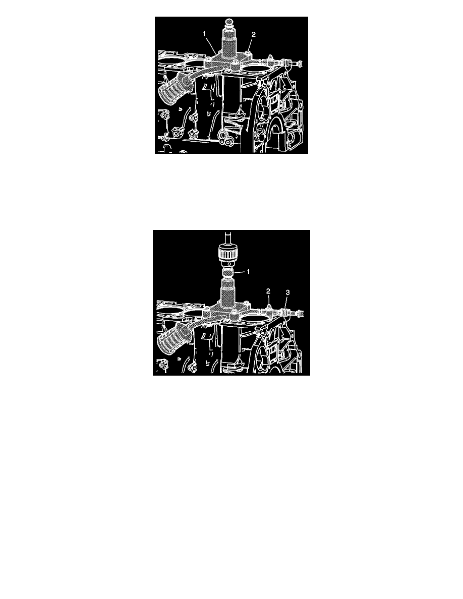
10. Place trim tool assembly EN 45680-411 onto the cylinder to be trimmed with the directional arrow (1) pointing in line with the crankshaft
centerline and the front of the block.
11. Install the 4 bolts EN 45680-414 (2) into the cylinder head bolt holes in the block.
Tighten
Tighten the bolts to 20 Nm (15 lb ft).
12. Fasten drive adapter EN 45680-866 (1) into the drill chuck.
13. Connect a compressed air supply 517-862 kPa (75-125 psi) to the male quick connect (3) located on trim tool assembly EN 45680-411. Turn the
compressed air valve (2) to the open position. This starts the venturi vacuum system that will catch the metal shavings.
14. Place drive adapter EN 45680-866 and drill assembly (1) vertically onto the drive adapter end of trim tool assembly EN 45680-411. Do not apply
downward force on the drill until full rotational speed has been reached. After reaching full rotational speed, gradually apply downward force until
the cutting action is complete in approximately 5 seconds.
15. Remove drive adapter EN 45680-866 (1) and drill assembly from the trim tool assembly EN 45680-411.
16. Turn off the compressed air valve (2).
17. Remove trim tool assembly EN 45680-411 from the engine block.
18. Remove any material shavings that may be found on the metal shaving catch plug EN 45680-413.
19. Wipe the cylinder bore sleeve and surrounding areas free of any powder residue and then remove the metal shaving catch plug EN 45680-413.