
Canyon 4WD V8-5.3L (2009)
Ignition Switch Lock Cylinder: Procedures
Key and Lock Cylinder Coding
This vehicle has two different types of ignition lock cylinders based on what type of steering column the vehicle is equipped with. The electric power
steering (EPS) option, usually found on 4 cylinder models, and the non EPS, usually found on 6 cylinder models, use different ignition lock cylinder
designs.
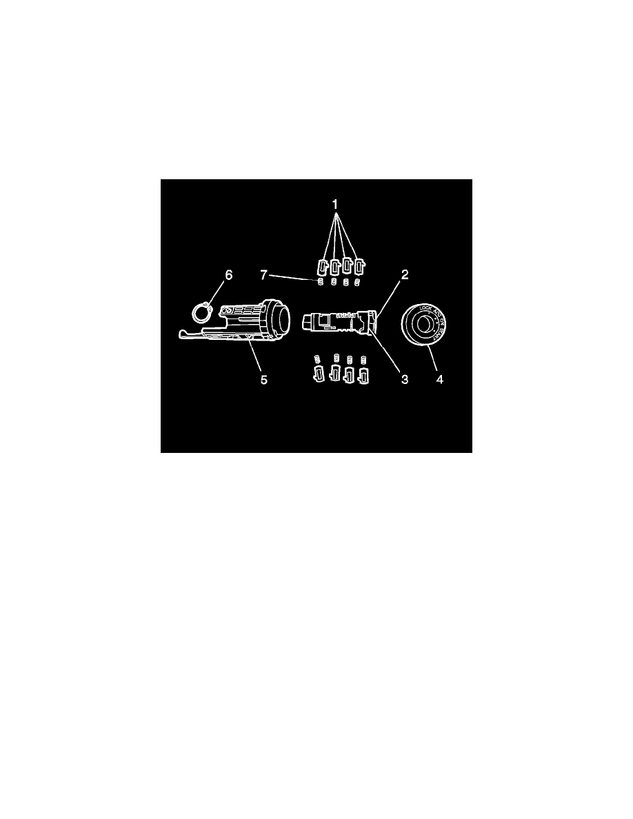
Ignition Lock Cylinder
The ignition lock cylinder uses all 10 key cut positions, 1-10 when counting from the key head. The tumbler orientations alternate in adjacent locations
from side to side with 5 tumblers on each side.
Important: The ignition lock cylinder tumblers (1) are not self retaining and must be held in place if the key is not fully inserted in the
lock cylinder (2), or until the lock cylinder (2) is assembled into the case assembly (5).
1. Hold the uncoded cylinder assembly (2) positioned so the side with the security plug (3) faces to the left of the key head.
2. Insert one tumbler spring (7) into each of the 4 tumbler spring holes.
3. The first tumbler (1) to be loaded will be key cut position 1, the first number in the key code. Install this tumbler in the tumbler slot closest to the
head of the lock cylinder (2), the end where the key is inserted.
4. Advancing one tumbler slot at a time, install tumblers 3, 5, and 7 sequentially on the same side as tumbler 1.
5. Turn the lock cylinder over and insert one tumbler spring (7) into each of the 4 tumbler spring holes on the opposite side of the lock cylinder.
6. Insert tumbler 2 into the tumbler slot closest to the head of the lock cylinder (2), the end where the key is inserted.
7. Advancing one tumbler slot at a time, install tumblers 4, 6, and 8 sequentially on the same side as tumbler 2.
8. Check for correct tumbler loading by holding the tumblers (1) in position and inserting the correct key into the lock cylinder. All tumblers (1)
should be flush with the housing of the lock cylinder.
9. Lightly lubricate the tumblers and small detent recessed areas the tumblers are in with GM Super Lube GM P/N 12346241 or equivalent light
lithium grease.
10. Take the slide piece and insert into the rotor. Ensure "Front of Sliding Piece" is facing the front face of the rotor. If the slide piece is installed
incorrectly, the key cannot insert into the rotor due to no access to the ramp.
11. Install the pivot pin into the actuator lever and install the actuator lever into the ignition lock cylinder housing. Ensure that the actuator lever is
inside of the lock cylinder housing at the end close to key insertion opening. Actuator lever should pivot on the pin against spring tension.
12. Insert the key into the coded lock cylinder (2) and hold the lock cylinder positioned so the side with the security plug (3) faces to the left of the key
head.