
Envoy 2WD L6-4.2L (2008)
Heated Glass Element: Testing and Inspection
Rear Window Defogger Malfunction
Diagnostic Instructions
*
Perform the Diagnostic System Check - Vehicle prior to using this diagnostic procedure. See: Testing and Inspection/Initial Inspection and
Diagnostic Overview/Diagnostic System Check - Vehicle
*
Review Strategy Based Diagnosis for an overview of the diagnostic approach.
*
Diagnostic Procedure Instructions provides an overview of each diagnostic category.
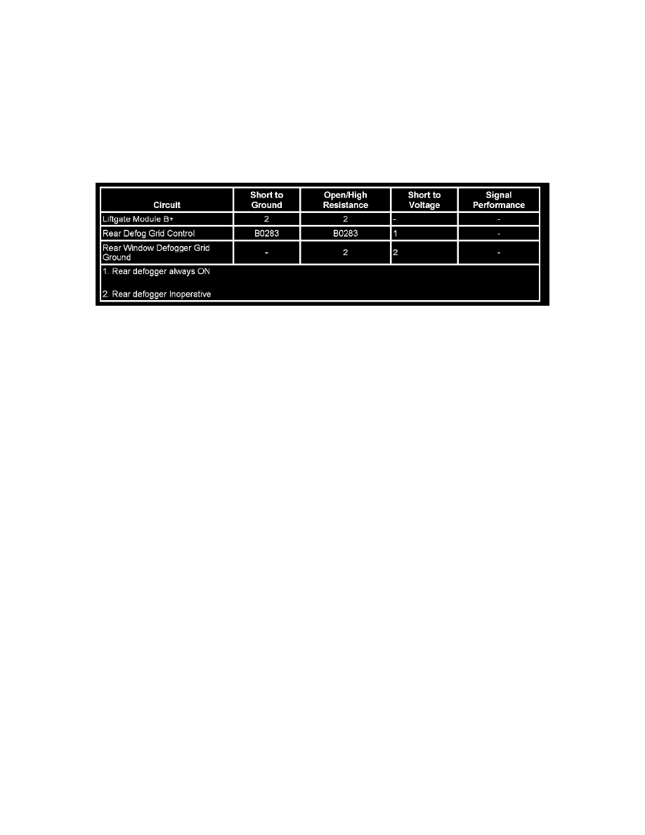
Diagnostic Fault Information
Circuit/System Description
The rear window defogger switch and indicator is an integral component of the HVAC control module. When the rear window defogger switch is
pressed, the HVAC control module responds by illuminating the defogger indicator and sending a GMLAN serial data message indicating a defog
request. This serial data message is received by the liftgate module (LGM). The LGM responds to the defog request by providing voltage to the rear
window defogger grid. Pressing the rear window defogger switch again will extinguish the indicator and send a GMLAN serial data message indicating
the defog deactivation command. The LGM responds by deactivating the defogger grid.
Circuit/System Verification
1. Ignition ON, observe the scan tool Rear Defrost Switch parameters while pressing and depressing the R DEF switch. The reading should change
between ON and OFF.
^
If the reading does not change between commanded states, replace the HVAC control module.
2. Ignition ON, command the rear window defogger ON and OFF with the scan tool. The rear window defogger should turn ON and OFF when
changing between the commanded states.
Circuit/System Testing
1. Ignition OFF, disconnect the X1 harness connector at the LGM
2. Ignition ON, verify a test lamp illuminates between the B+ circuit terminal A and ground.
^
If the test lamp does not illuminate, test the B+ circuit for a short to ground or an open/high resistance. If the circuit tests normal and the LGM
#2 fuse is open, replace the LGM.
3. Ignition OFF, reconnect the harness connector at the LGM and disconnect the harness connector at the rear window defogger grid.
4. Test for less than 1.0 ohm between the ground circuit terminal A and ground.
^
If greater than the specified range, test the ground circuit for an open/high resistance.
5. Connect a test lamp between the rear defog element supply voltage circuit terminal A and ground.
6. Ignition ON, command the rear defog ON and OFF with a scan tool. The test lamp should turn ON and OFF when changing between the
commanded states.
^
If the test lamp is always ON, test the rear defog element supply voltage circuit for a short to voltage. If the circuit tests normal, replace the
LGM.
^
If the test lamp is always OFF, test the rear defog element supply voltage circuit for a short to ground or an open/high resistance. If the circuit
tests normal, replace the LGM.
7. If all circuits test normal, test or replace the rear window defogger.