
Envoy 2WD V6-4.3L VIN W (1998)
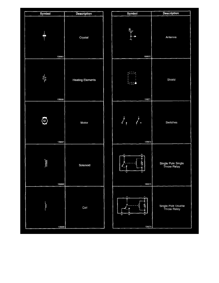
Electrical Symbols (Part 4 Of 4)
Circuit Descriptions
The circuit description describes how the system works electrically. It details how power, ground, inputs, and outputs are supplied to the system's related
components. The circuit description also explains the communication and interaction of all components that affect the operation of the system.
Battery positive voltage is applied at all times to the horn relay terminals 85 and 30. Pressing the horn switch grounds the horn relay coil on CKT 28
(BLK). The relay coil can also be grounded on CKT 28 (BLK) by the Dash Integration Module (DIM). The horn relay applies battery positive voltage to