
Envoy 2WD V6-4.3L VIN W (1998)
Body Control Module: Scan Tool Testing and Procedures
Class 2 Serial Data Communication
The Class 2 network continually monitors various subsystems (i.e. ATC, BCM, HVAC, IPC, PCM, and VCM) and operating conditions for possible
system malfunctions. Compare the system conditions against standard operating limits in order to detect certain circuit and component malfunctions. A 5
digit alphanumeric Diagnostic Trouble Code (DTC) is stored in the computer memory. When a malfunction is detected by this self-diagnostic system,
the DTC(s) may later be retrieved by the service technician using a scan tool. The scan tool may aid the technician in repairing various subsystems.
Data Link Connector (DLC)
The 16 pin DLC is wired to the body control module. The 16-pin DLC is located under the dash panel on the left side. The DLC connector has terminals
that are used in order to connect to a scan tool. The following list shows some common uses of the scan tool:
^
Identifying stored Diagnostic Trouble Codes (DTCs)
^
Clearing DTCs
^
Performing output control tests
^
Reading serial data
Diagnostic Trouble Code (DTC) Diagnosis
This section uses the following items in order to direct you in performing specific tests in order to locate and repair the problem:
^
Diagnostic tables
^
Wiring diagrams
^
Descriptive text
The diagnostic table is a step by step procedure used in order to determine the circuit or the component that is the source of the problem. The following
items are located above the diagnostic table:
^
Wiring diagrams
^
Descriptive text
^
Test conditions
^
Failure conditions
^
Actions taken when a DTC is set
When the Diagnostic Trouble Codes (DTCs) are set, the BCM detects a malfunction in a particular circuit or other system. Other system malfunctions
are generally (but not exclusively) reported to the BCM via Class 2 data message. The BCM is programmed with routines for internal checks that the
BCM follows only under prescribed conditions (called test conditions). When these conditions exist, the BCM inspects certain circuits or systems for a
malfunction. These inspections are called failure conditions or conditions for setting the DTC. When these conditions are true, a DTC is set. The BCM
turns the SECURITY Malfunction Indicator Lamp (MIL) to the ON position for the Passlock system related malfunctions. Refer to the applicable DTC
table for procedures and details.
General Information
The typical scan tool readings of Body Control Module (BCM) data will assist in diagnosing a problem. The scan tool data displays can be viewed while
the vehicle is being driven.
The typical scan tool data definitions represent general information displayed on the scan tool regarding the following items:
^
BCM functions
^
Ignition inputs
^
Basic operating conditions
The data messages and menu headings displayed on the scan tool are defined below.
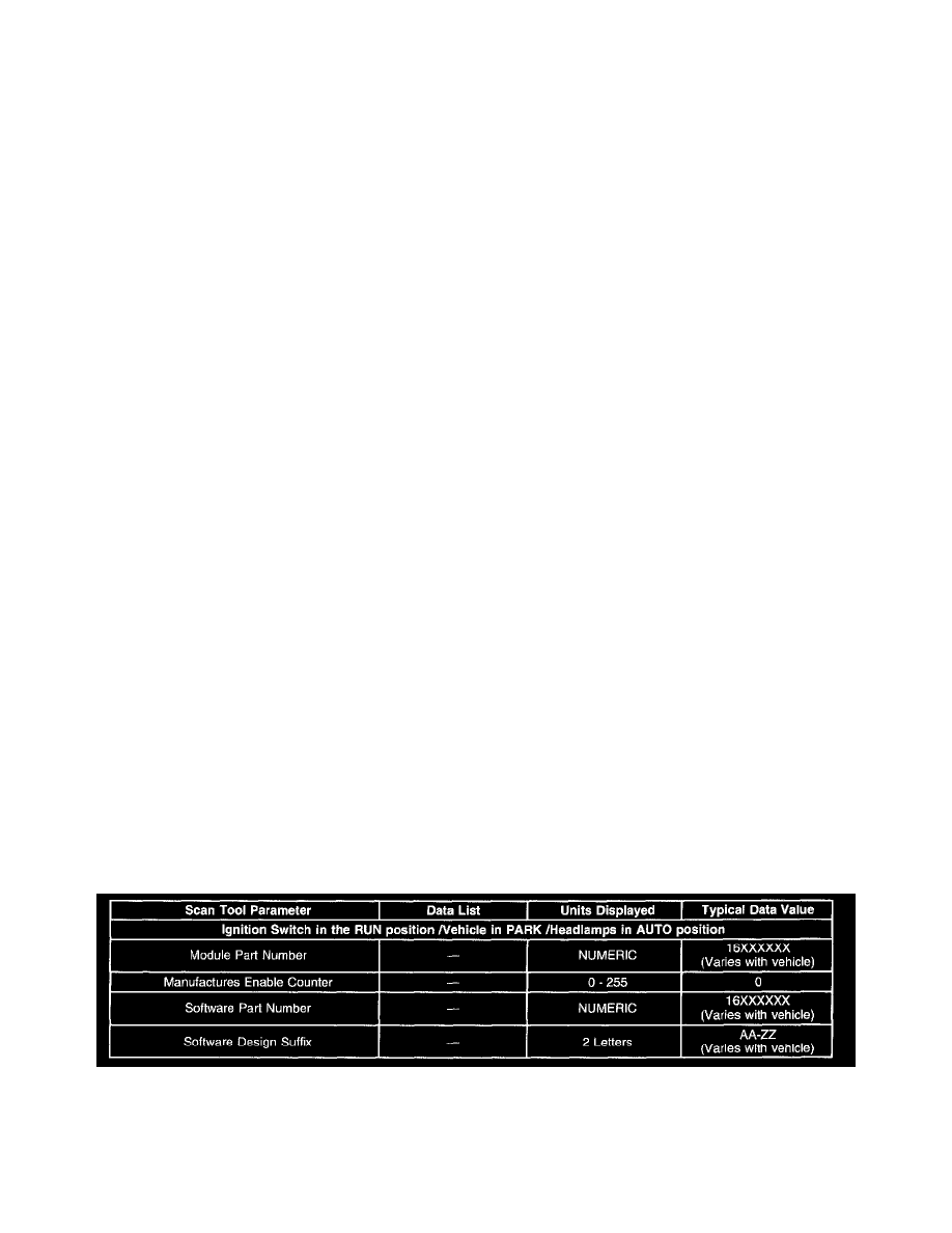
Module Information 1
Module Information 1
MODULE PART NUMBER
Range: 16XXXXXX
This information refers to the part number assigned to the BCM that is currently in the vehicle.