
Envoy 2WD V6-4.3L VIN W (1998)
Vehicle Control Module: Service and Repair
Vehicle Control Module (VCM) Replacement/Programming
IMPORTANT: Disconnecting the VCM will not erase the Crankshaft Position (CKP) System Variation Learn as long as the ignition switch is in the
OFF position.
REMOVAL PROCEDURE
1. Disconnect the negative battery cable.
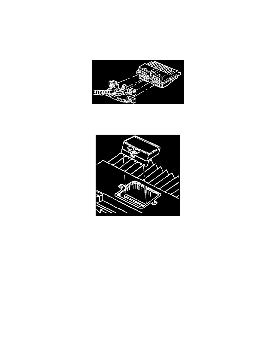
2. Pull the spring retainer up and over the rail of the VCM. Slide the VCM out of the bracket at an angle.
VCM Harness Connections
3. Remove the connectors from the VCM.
4. Remove the VCM access cover.
5. Gently pinch the retaining clip and pull upward to remove the Electronic Spark Control module/PROM.
6. Set the Electronic Spark Control module/PROM aside carefully.
NOTE: The Electronic Spark Control module/PROM will be reused in the replacement VCM.
7. Do not open the Electronic Spark Control module/PROM.
8. Remove the new VCM from the packaging. Check the service number in order to make sure the number matches the defective VCM's number.
INSTALLATION PROCEDURE
NOTICE: In order to prevent possible electrostatic discharge (ESD) damage to the VCM, do not touch the connector pins or soldered components on
the circuit board.
IMPORTANT: Press only on the ends of the KS Calibration PROM. Gently press on the Knock Sensor (KS) Calibration PROM until it is firmly
seated in the socket. Listen for the click.
1. Align the notches of the Electronic Spark Control module/PROM with the notches in the Electronic Spark Control module/PROM socket.
2. Install the Electronic Spark Control module/PROM in the Electronic Spark Control module/PROM socket.
3. Install the access cover on the VCM.
4. Install the VCM in the engine compartment.
5. Install the connectors to the VCM.
6. The MIL, antilock and brake lamps will continue to be enabled until the VCM is programmed. Once the programming is complete, the lamps will
turn off and normal operation will occur.
7. Connect the negative battery cable.