
Envoy 2WD V6-4.3L VIN W (1998)
Fluid Pressure Sensor/Switch: Description and Operation
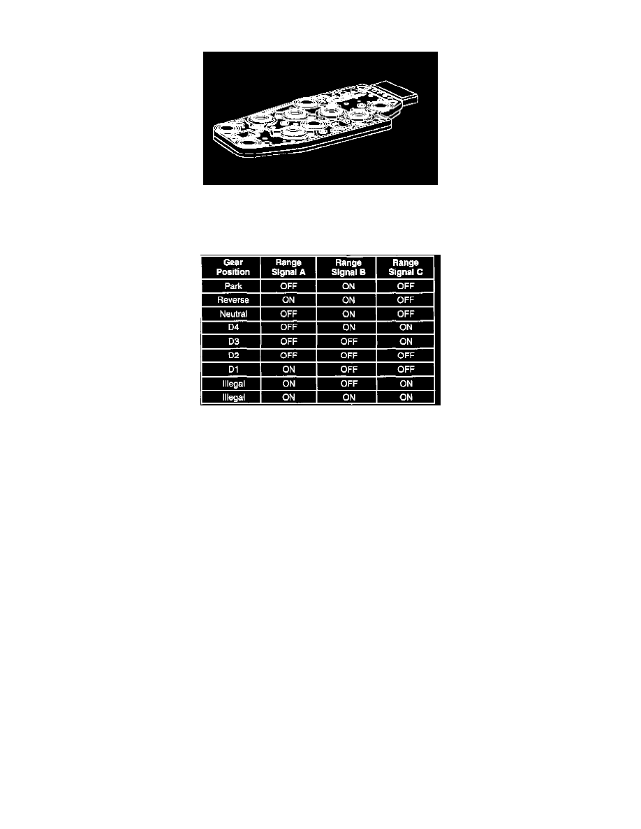
TRANSMISSION FLUID PRESSURE (TFP) MANUAL VALVE POSITION SWITCH
IMPORTANT: Seven valid combinations and two invalid combinations are available from the Transmission Fluid Pressure (TFP) manual valve
position switch.
TFP Manual Valve Position Switch Logic Line Pressure
Refer to the TFP Manual Valve Position Switch Logic table for valid/invalid combinations for range signal circuits A, B and C.
The transmission fluid pressure (TFP) manual valve position switch is a set of five pressure switches on the control valve body that sense whether
fluid pressure is present in five different valve body passages. The combination of which switches are open and closed is used by the PCM in order to
determine actual manual valve position. The TFP manual valve position switch, however, cannot distinguish between PARK and NEUTRAL because
the monitored valve body pressures are identical in both cases. The switches are wired to provide three signal lines that are monitored by the PCM.
These inputs are used to help control line pressure, torque converter clutch apply and shift solenoid valve operation. Voltage at each of the signal lines
is either zero or twelve volts.
In order to monitor the TFP manual valve position switch operation, the PCM compares the actual voltage combination of the switches to a TFP
combination table stored in its memory. If the PCM sees one of two illegal voltage combinations, a DTC P1810 will result. A DTC P1810 indicates a
short circuit condition in either the range signal A or the range signal C circuits.
The TFP manual valve position switch signal voltage can be measured from each pin-to-ground and compared to the combination table. On the
automatic transmission (A/T) wiring harness assembly, pin N is range signal A, pin R is range signal B, and pin P is range signal C. With the A/T
wiring harness assembly connected and the engine running, a voltage measurement of these three lines will indicate a high reading (near 12 volts)
when a circuit is open, and a low reading (zero volts) when the circuit is switched to ground.
The transmission fluid temperature (TFT) sensor is part of the TFP manual valve position switch assembly.