
Envoy 2WD V6-4.3L VIN W (1998)
7.1. Do not add lubricant. Roller type bearings are permanently lubricated.
7.2. If the bearing is damaged or dry, replace the bearing using a small bearing puller.
7.3. Recess the bearing 1.6 mm (0.06 in) into the housing.
8. Install the shift lever shaft to the thrust collar.
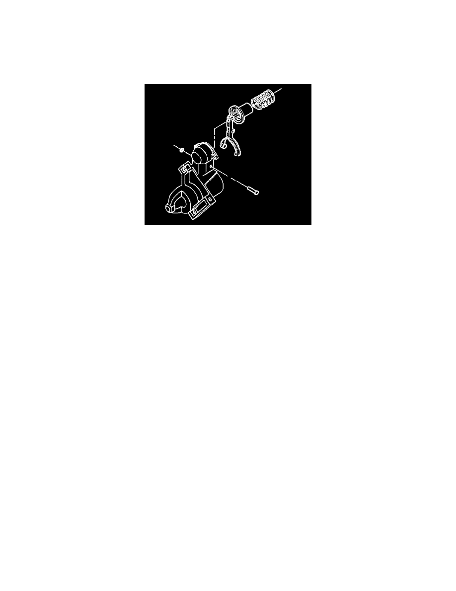
9. Install the armature and the drive components into the drive end housing.
10. Install the shift lever shaft in the drive end housing.
11. Install the shaft retainer.
12. Place the return spring onto the plunger.
13. Press the return spring in order to install the solenoid over the plunger.
14. Align the solenoid with the drive end housing.
15. Install the screws.
Tighten
Tighten the screws to 6.5 N.m (60 lb in).
NOTICE: Refer to Fastener Notice in Cautions and Notices.
16. Replace any damaged brushes.
17. Tighten the brushes.
18. Clean the brush contact faces in the frame and field with a soft cloth.
19. Install the frame and field components as follows:
19.1. Apply sealer to the solenoid flange where it contacts the frame and field.
19.2. Push the brushes into the brush holders and hold.
19.3. Install the frame and the field components over the armature.
19.4. Align the frame and field components to the drive end housing.
19.5. Release the brushes onto the commutator.
19.6. Inspect that all four brushes move freely in the holders.
19.7. Inspect that the brushes are in contact with the commutator.
20. Install the brake washer onto the armature shaft.
21. Inspect the bearing in the commutator end frame.
^
Do not lubricate the bearing. Roller type bearings are permanently lubricated.
^
Replace the bearing if it is damaged or dry using a small bearing puller.
^
Recess the bearing 2 mm (0.08 in) into the housing.
22. Install the commutator end frame onto the armature shaft.
23. Align the commutator end frame and the frame with field.
24. Install the identification tag onto one through bolt.
25. Install the starter motor through bolts.
If the through bolts have different heads, install as noted during disassembly.
Tighten
Tighten the bolts to 8.5 N.m (75 lb in).
26. Inspect the drive pinion clearance.
Refer to Starter Pinion Clearance Check in Engine Electrical.
27. Install the solenoid terminal field lead.
Tighten