
Envoy 2WD V6-4.3L VIN W (1998)
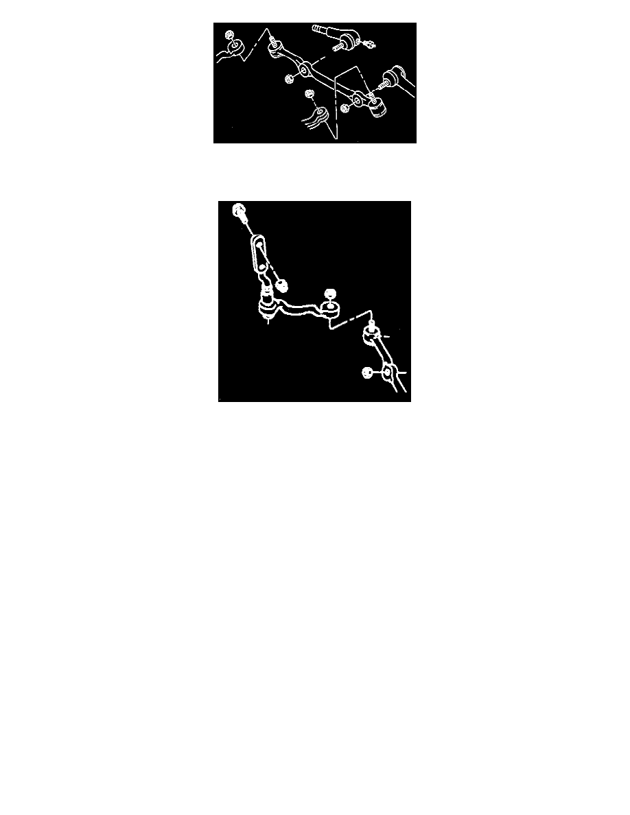
2. Inner tie rods ball studs from the relay rod. Refer to "Tie Rod Replacement."
3. Relay rod ball stud nut at the pitman arm.
4. Relay rod ball stud from the pitman arm using J 24319-B.
5. Relay rod ball stud nut at the idler arm.
6. Relay rod ball stud from the idler arm using J 24319-B.
7. Relay rod.
Inspect
-
Threads on the tie rod and the tie rod end for damage.
-
Ball stud threads for damage.
-
Ball stud seals for excessive wear.
Clean
-
Threads on the ball stud and the ball stud nut.
Install or Connect
^
Tools Required:
-
J 29193 Steering Linkage Installer (12 mm)
-
J 29194 Steering Linkage Installer (14 mm)
1. Relay rod ball stud to the idler arm. Make sure the seal is on the stud. Tighten J 29193 or J 29194 to 54 Nm (40 ft. lbs.) in order to seat the taper.
2. Nut to the relay rod ball stud at the idler arm.
-
Tighten nut to 47 Nm (35 ft. lbs.).
3. Relay rod ball stud to the pitman arm. Make sure the seal is on the stud. Tighten J 29193 or J 29194 to 54 Nm (40 ft. lbs.) in order to seat the
taper.
4. Nut to the relay rod ball stud at the pitman arm.
-
Tighten nut to 47 Nm (35 ft. lbs.).
5. Inner tie rod ball studs to the relay rod.
-
Make sure the seal is on the stud. Tighten J 29193 or J 29194 to 54 Nm (40 ft. lbs.) in order to seat the taper.
6. Nut to 47 Nm (35 ft. lbs.).
-
Tighten nut to 47 Nm (35 ft. lbs.).
Adjust
-
Toe-in.