
Envoy 2WD V6-4.3L VIN W (1998)
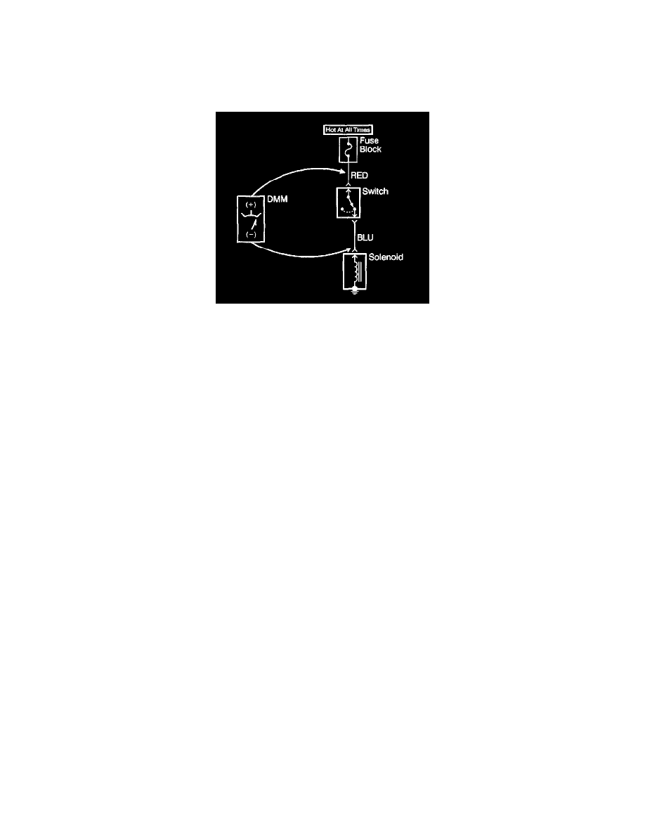
3. Connect the positive lead of the DMM to the point of the circuit to be tested.
4. Connect the negative lead of the DMM to a good ground.
5. Operate the circuit.
6. The DMM displays the voltage measured at that point.
Measuring Voltage Drop
NOTE: Refer to Test Probe Notice in Cautions and Notices.
The following procedure determines the difference in voltage potential between two points.
1. Set the rotary dial of the DMM to the V (DC) position.
2. Connect the positive lead of the DMM to one point of the circuit to be tested.
3. Connect the negative lead of the DMM to the other point of the circuit.
4. Operate the circuit.
5. The DMM displays the difference in voltage between the two points.
Testing For Continuity
The following procedures verify good continuity in a circuit.
With a DMM
1. Set the rotary dial of the DMM to the Q position.
2. Disconnect the power feed (i.e. fuse, control module) from the suspect circuit.
3. Disconnect the load.
4. Press the MIN MAX button on the DMM.
5. Connect one lead of the DMM to one end of the circuit to be tested.
6. Connect the other lead of the DMM to the other end of the circuit.
7. If the DMM displays low or no resistance and a tone is heard, the circuit has good continuity.
With a Test Lamp
IMPORTANT: Only use the test lamp procedure on low impedance power and ground circuits.
1. Remove the power feed (i.e. fuse, control module) from the suspect circuit.
2. Disconnect the load.
3. Connect one lead of the test lamp to one end of the circuit to be tested.
4. Connect the other lead of the test lamp to battery positive voltage.
5. Connect the other end of the circuit to ground.
6. If the test lamp illuminates (full intensity), then the circuit has good continuity.
Testing For Electrical Intermittents
Perform the following procedures while wiggling the harness from side to side. Continue this at convenient points (about 6 inches apart) while watching
the test equipment.
^
Testing for Shod to Ground
^
Testing for Continuity
If the fault is not identified, perform the procedure below using the MIN MAX feature on the J 39200 DMM. This feature allows you to manipulate the
circuit without having to watch the J 39200. The J 39200 will generate an audible tone when a change is detected.
IMPORTANT: The J 39200 must be used in order to perform the following procedure since the J 39200 can monitor current, resistance or voltage
while recording the minimum (MIN), and maximum (MAX) values measured.