
Envoy 2WD V8-5.3L (2007)
Step 1 - Step 10
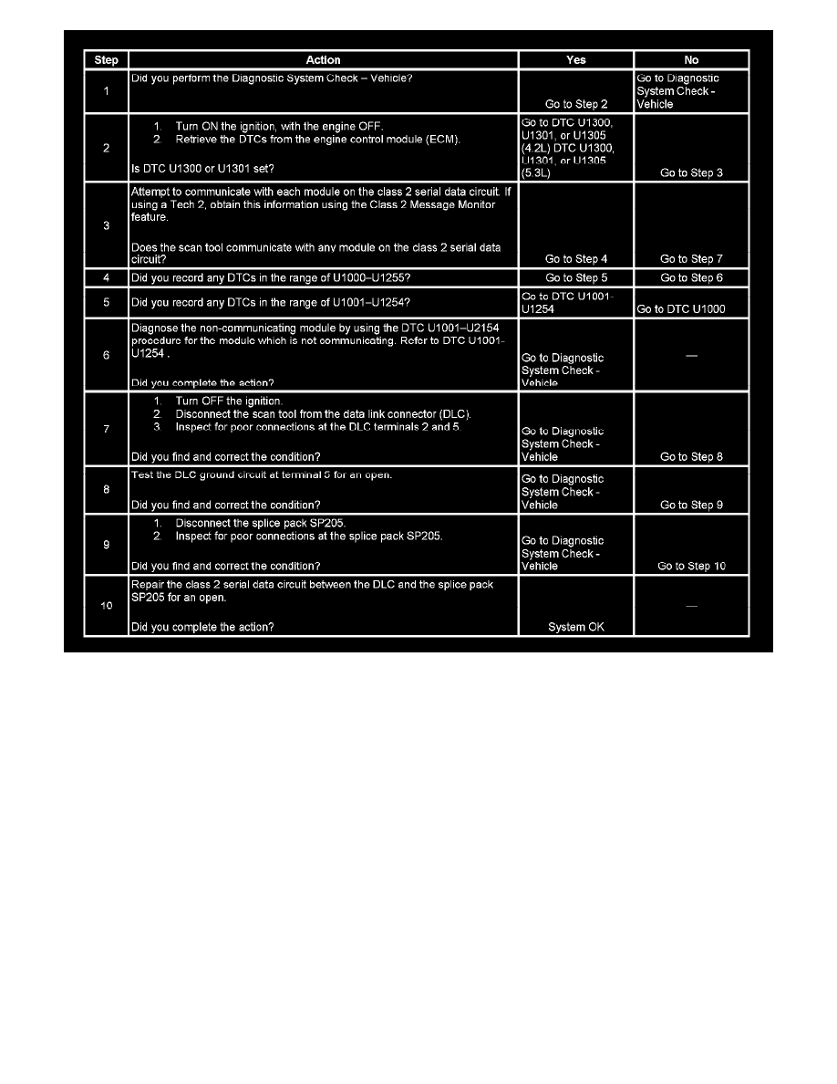
The numbers below refer to the step numbers on the diagnostic table.
2. A current DTC, U1300 or U1301, may be retrieved only from the engine control module (ECM), because the ECM is connected to both class 2
and high speed GMLAN buses, but it communicates with the scan tool on high speed GMLAN bus only.
3. A partial malfunction in the class 2 serial data circuit uses a different procedure from a total malfunction of the class 2 serial data circuit. The scan
tool communicates with the following modules on the class 2 serial data circuit:
-
The body control module (BCM)
-
The communication interface module (OnStar(R)), w/UE1
-
The digital radio receiver (DRR), w/U2K
-
The driver door module (DDM)
-
The driver seat module (DSM), w/AAB
-
The DVD player
-
The electronic brake control module (EBCM)
-
The end gate module (EGM), for XUV
-
The HVAC control module
-
The HVAC control module - rear auxiliary
-
The inflatable restraint sensing and diagnostic module (SDM)
-
The instrument panel cluster (IPC)
-
The liftgate control module (LGM)
-
The passenger door module (PDM)
-
The radio
-
The transfer case shift control module (TCSCM), w/4WD
-
The theft deterrent control module (VTD), w/BAE