
Envoy 4WD V8-5.3L VIN P (2004)
Important: When installing bolts throughout this procedure, be sure to use the correct bolt size and length in the correct location as specified.
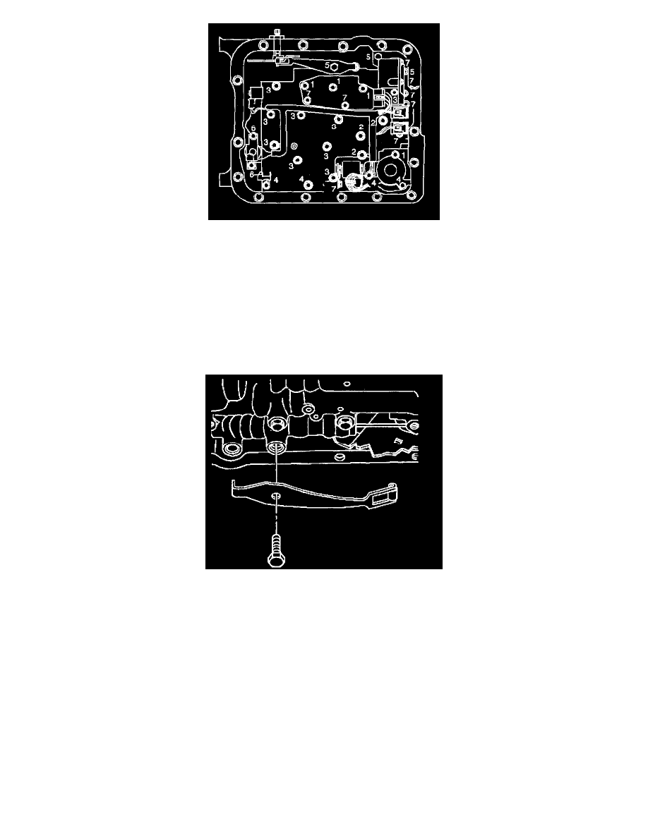
5. Do not install the transmission fluid indicator stop bracket and bolt at this time. Install but do not tighten the control valve body bolts which retain
only the valve body directly. Each numbered bolt location corresponds to a specific bolt size and length, as indicated by the following:
^
M6X1.0X65.0(1)
^
M6 X 1.0 X 54.4(2)
^
M6X1.O X47.5 (3)
^
M6X1.O X35.0 (4)
^
M8 X 1.0 X 20.0 (5)
^
M6 X 1.0 X 12.0(6)
^
M6 X 1.0 X 18.0(7)
6. Install the manual detent spring.
7. Install but do not tighten the manual detent spring retaining bolt.