
G 1500 1/2 Ton Van V8-5.7L VIN R (1996)
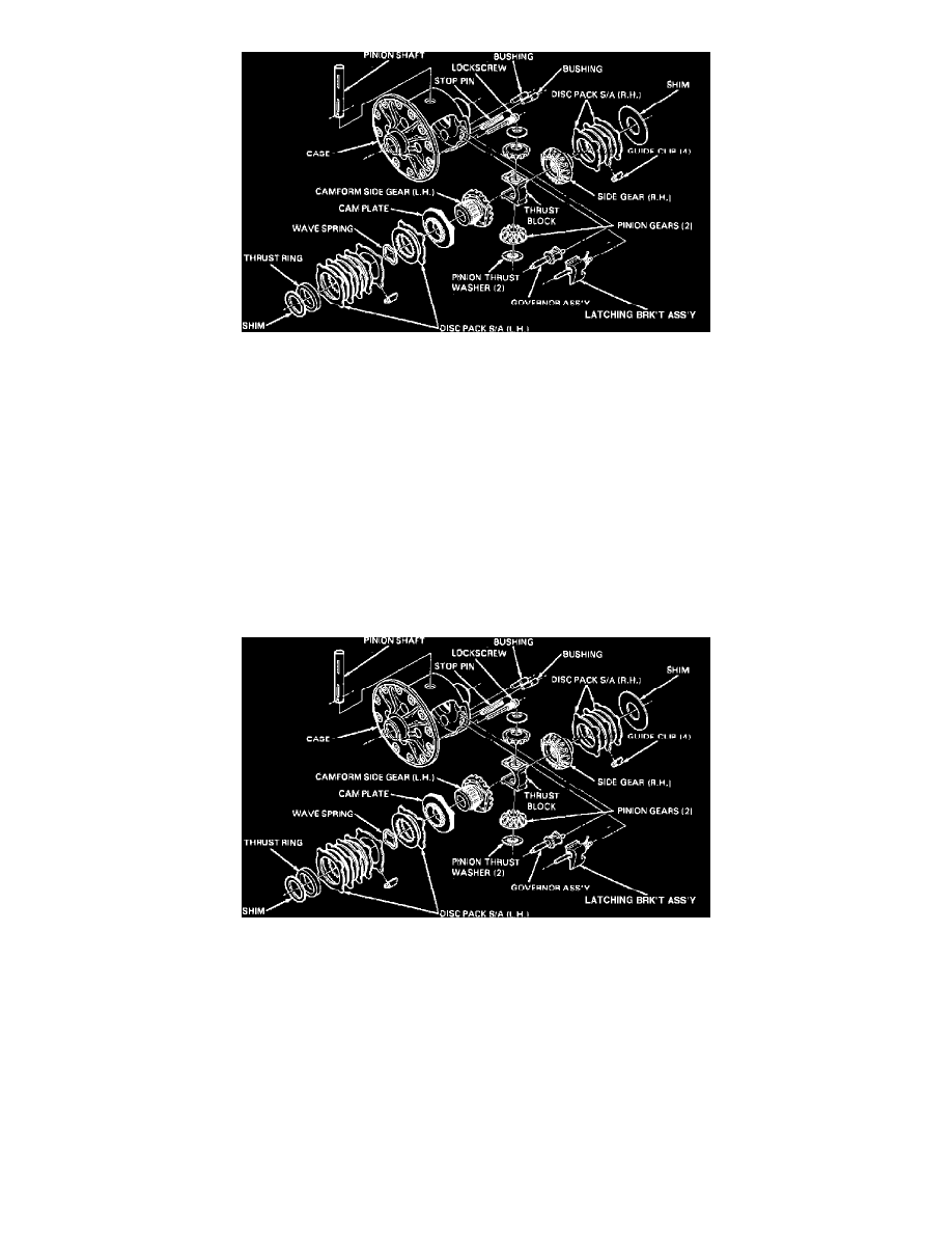
Fig. 5 Eaton locking differential exploded view
6.
Assemble 2 eared discs, 1 splined disc and wave spring onto cam plate as shown in
Fig. 5. If components are reused, they must be installed in
original position.
7.
Alternately assemble 3 splined and 4 eared discs on cam gear hub, as shown in
Fig. 5.
8.
Mount cam gear assembly in press and position thrust ring over gear hub.
9.
Compress disc pack to prevent splined disc from being trapped, then press thrust ring onto gear until seated against shoulder of gear.
10.
Inspect assembly to ensure that discs are properly assembled and that first splined disc (large spline) is properly located on cam plate.
Side Gear (RH) Clutch Service
1.
Remove shim and disc pack from gear keeping components in order.
2.
Inspect discs and guide clips and replace as needed.
3.
Inspect side gear and shim. If either component is scored or excessively worn, inspect case and replace entire assembly if case is defective.
If
either side gear or shim must be replaced, shim thickness must be determined. Refer to Shim Selection. See: 9 1/2 Inch Ring
Gear/Overhaul/Eaton Locking/Shim Selection
Fig. 5 Eaton locking differential exploded view
4.
Alternately assemble splined and eared discs on side gear hub as shown in
Fig. 5. If components are reused, they must be installed in original
position.
5.
Install original shim or new shim of equal thickness.
Shim Selection
CAM GEAR SHIM SELECTION
If cam gear is replaced, or if original cam gear shim thickness cannot be determined, shim must be selected to maintain proper backlash with
differential pinions using following procedure.
1.
Install disc pack guide clips, then mount cam gear assembly in differential case using original shim.
2.
Install differential pinions and thrust washers in installed position in case, then insert pinion shaft and retain shaft with lock screw.
If pinion shaft
cannot be inserted, replace cam gear shim with one of less thickness.
3.
Index one tooth of pinion closest to lockscrew so that it points downward, perpendicular to case flange.