
G 1500 1/2 Ton Van V8-5.7L VIN R (1996)
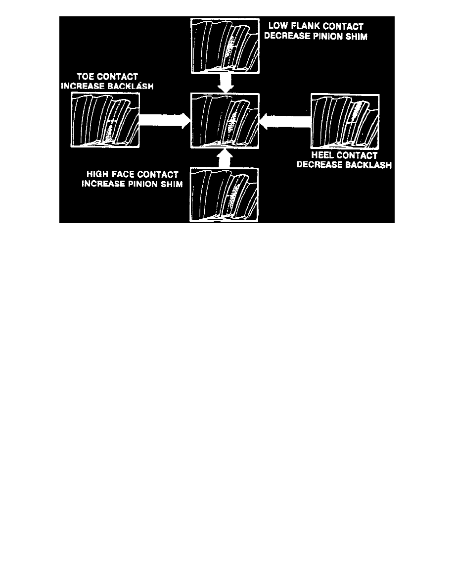
Fig. 6 Gear Tooth Contact Pattern Check.
16. Examine gear tooth contact pattern, referring to Fig. 6, and correct assembly adjustments as needed.
17. Install housing cover, using a new gasket, and torque attaching bolts to 35 ft. lbs.
18. Install rear universal joint, then the axle shafts.
19. Fill axle with specified lubricant.
Cleaning & Inspection
1.
Clean components in suitable solvent and blow dry with compressed air, noting the following:
a. Do not use brush when cleaning bearings.
b. Do not ``spin dry'' bearings as bearings will be damaged.
c. Lightly lubricate components after cleaning to retard corrosion.
d. Keep all components in order to ensure proper assembly.
2.
Inspect gears for cracks, chipped or broken teeth, wear and scoring. Replace gears that are damaged or excessively worn.
3.
Inspect differential case for cracks, damage, distortion, worn side gear bores and scored bearing surfaces, and replace as needed.
4.
Inspect housing for scored bearing mount surfaces, cracks and distortion, and replace as needed. Ensure that housing is clean and free from foreign
material.
5.
Inspect bearing rollers and races for pitting, scoring, overheating and damage.
6.
Mate each bearing with race and check operation.
7.
Replace any bearing assembly that is damaged, excessively worn, or that fails to operate smoothly.
8.
Mount differential case along with side bearings and ring gear in housing, adjust side bearings to zero preload and check ring gear runout with dial
indicator bearing against machined edge of gear.
9 3/4 Inch Ring Gear
1. Remove differential bearing cups and tag for assembly reference.
2. Secure differential in a suitable vise and drive out pinion shaft lockpin.
3. Remove differential bearing cone and roller using a suitable puller and plug tool No. J-8107-3 or equivalent. Tag cone and rollers for assembly
reference.
4. Remove spacer, pinion shaft, pinions, side gears and thrust washers from differential case.
5. Remove ring gear attaching bolts and the ring gear.
6. Position differential side gears and new thrust washers in differential case.
7. Position differential pinions and new thrust washers in differential case.
8. Install pinion shaft in case, then align hole in shaft with hole in case and drive lockpin into position. Peen hole to prevent pin from falling from
case.
9. Install ring gear and torque bolts alternately and evenly to 110 ft. lbs.
10. Position side bearings onto case and seat bearings using a suitable driver.
11. Determine total amount of shims needed to set backlash as follows:
a. Place differential case in carrier and install bearing caps in original position. Tighten caps just enough to retain in place.