
G 2500 3/4 Ton Van V6-262 4.3L (1986)
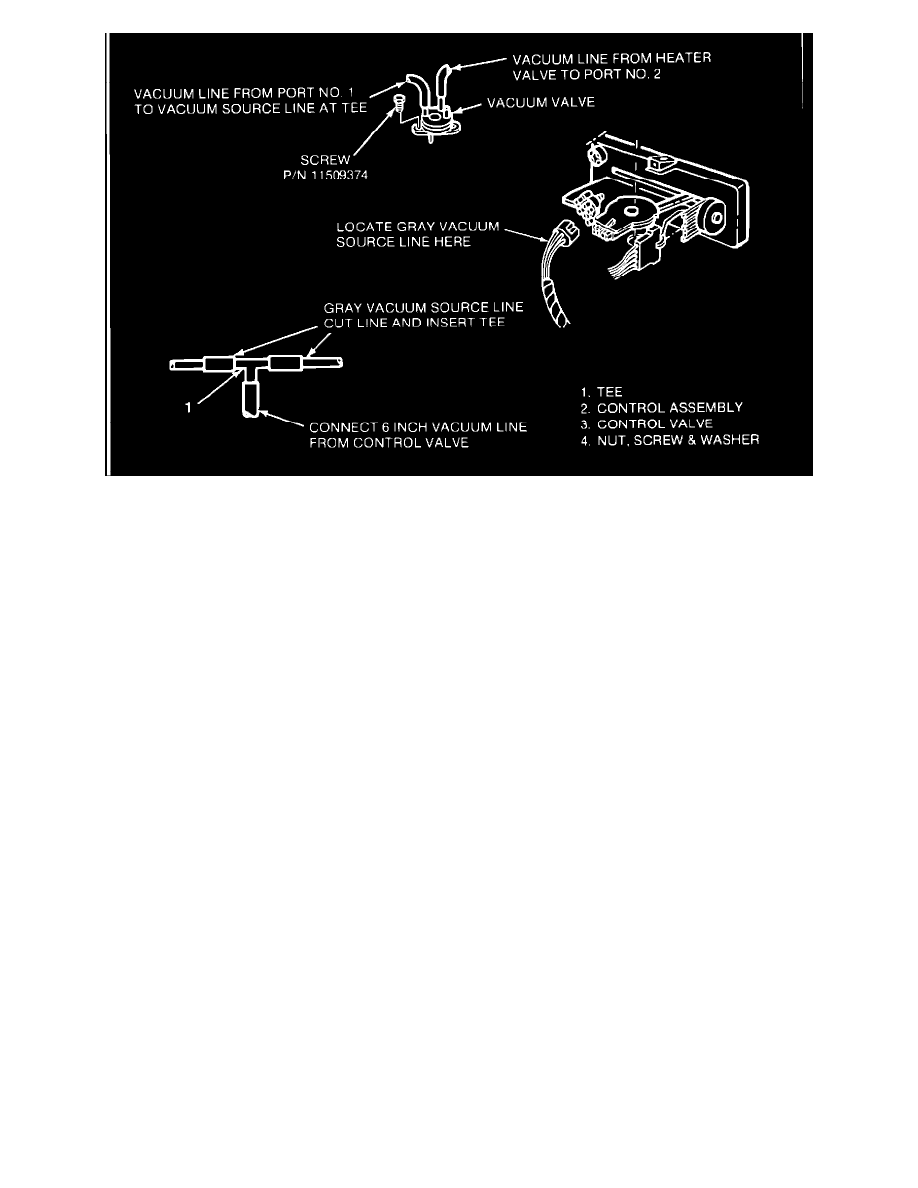
FIGURE 4
IIA. VACUUM VALVE INSTALLATION (Figures No. 2,3, and 4)
a)
Drill a 7/32", diameter hole in dash wall next to hood latch cable (Figure No. 2) and deburr edges of hole.
b)
Install vacuum hose (1) on heater water by-pass valve (2) and route with A/C harness (3) to bole in dash. Band strap
(4)
hose to harness as shown. Apply sealer around hose as necessary to seal.
c)
Remove engine cover and instrument panel lower extension for next step.
d)
Remove instrument cluster trim plate.
e)
Remove HVAC control assembly (Figure No. 3) and slide assembly out of dash sufficiently to gain access to rear of the unit.
f
Install vacuum valve on heater control
assembly (Figure No. 3). Slide one mounting ear on valve under the slot on control assembly. Install and tighten screw in opposite ear. (Note:
Pin on bottom of vacuum valve must fit into slot on the temperature control arm.)
g)
Locate gray colored vacuum source line at A/C control assembly (Figure No. 4).
h)
Cut gray vacuum source line and insert vacuum tee (1) (Figure No. 4). Attach 6" long vacuum line from vacuum tee to vacuum valve inlet
port 1. Attach vacuum hose from heater valve to vacuum valve outlet port 2 (Figure No. 4).
Notice:
Port numbers are identified on valve.
i)
Reinstall control assembly in dash.
j)
Reinstall instrument cluster trim plate.
k)
Reinstall engine cover and instrument panel lower extension.
l)
Refill radiator with coolant.
m)
Run engine and check for coolant leaks.
n)
Place temperature control arm in high heat position, check the position of the lever on the heater water by-pass valve. It should be in the extended
position. Place control selector in the full cold position and recheck valve. Lever should be in the retracted position.