
G 2500 3/4 Ton Van V6-262 4.3L VIN Z (1992)
12.
Remove reaction body retainer, reaction body, reaction disc and reaction piston from reaction body, Fig. 8.
13.
Remove air valve spring and reaction bumper from end of air valve pushrod, Fig. 8.
14.
Remove retaining ring from air valve pushrod assembly.
15.
Remove air valve pushrod assembly by inserting a screwdriver through the pushrod eyelet and pulling pushrod assembly straight out.
16.
Remove filter, retainer and O-ring from air valve pushrod assembly.
17.
Inspect all parts for corrosion, nicks, cracks, cuts, scoring, distortion or excessive wear. Replace as necessary.
18.
Clean all parts in denatured alcohol and dry with clean compressed air. Do not immerse power piston and pushrod assembly in alcohol.
Assembly
1.
Install lubricated O-ring onto air valve pushrod assembly.
2.
Install air valve pushrod into the power piston.
3.
Install retainer and seat.
4.
Install filter over pushrod eyelet and into power piston.
5.
Install retaining ring onto air valve pushrod assembly.
6.
Install reaction bumper, air valve spring, reaction piston and reaction disc onto reaction body.
7.
Install reaction body, then reaction body retainer.
8.
Lubricate inside diameter of secondary diaphragm lip, inside diameter of primary diaphragm lip and the secondary piston bearing with a thin layer
of silicone grease.
9.
Install secondary diaphragm into the secondary support plate, Fig. 8.
10.
Install secondary diaphragm and secondary support plate over the power piston and pushrod assembly.
11.
Install secondary piston bearing into housing divider with flat surface of bearing on the same side as the six raised lugs on the divider.
12.
Install secondary piston bearing and housing divider over power piston assembly and pushrod.
13.
Install primary diaphragm into the primary support plate, Fig. 8.
14.
Fold primary diaphragm up away from the primary support plate, then install primary diaphragm and support plate over power piston and pushrod
assembly.
15.
Fold primary diaphragm back into position and pull the outside edge of diaphragm over formed flange of housing divider.
16.
Install new diaphragm retainer. Ensure retainer is fully seated.
17.
Install silencer, reaction retainer and piston rod.
18.
Lubricate inside and outside diameters of primary piston bearings with silicone grease.
19.
Install primary piston bearing into rear housing.
20.
Install power piston assembly into rear housing, then the return spring.
21.
Mount housing to holding fixture and turn fixture handle to lock the front and rear housings, Fig. 4.
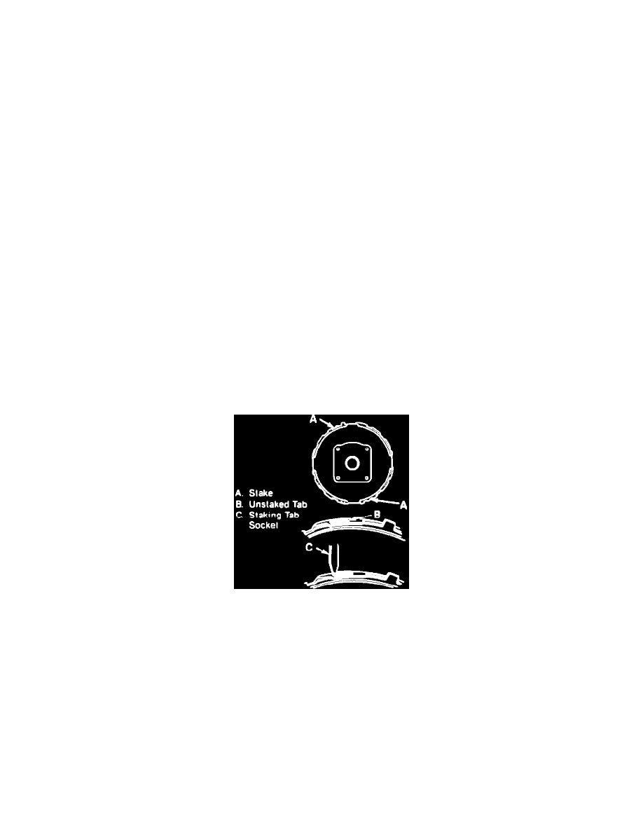
Fig. 5 Brake Booster Lock Tab & Staking Positions
22.
Stake housing in locations shown, Fig. 5. Do not stake a tab that has been staked previously.
23.
Lubricate inside and outside edges of grommet and front housing seal, then install grommet and seal.
24.
Install vacuum check valve, silencer and boot.
25.
Ensure piston rod depth is within specifications using gauge tool No. J-37839 or equivalent.