
G 2500 3/4 Ton Van V6-262 4.3L VIN Z (1992)
Intake Manifold: Service and Repair
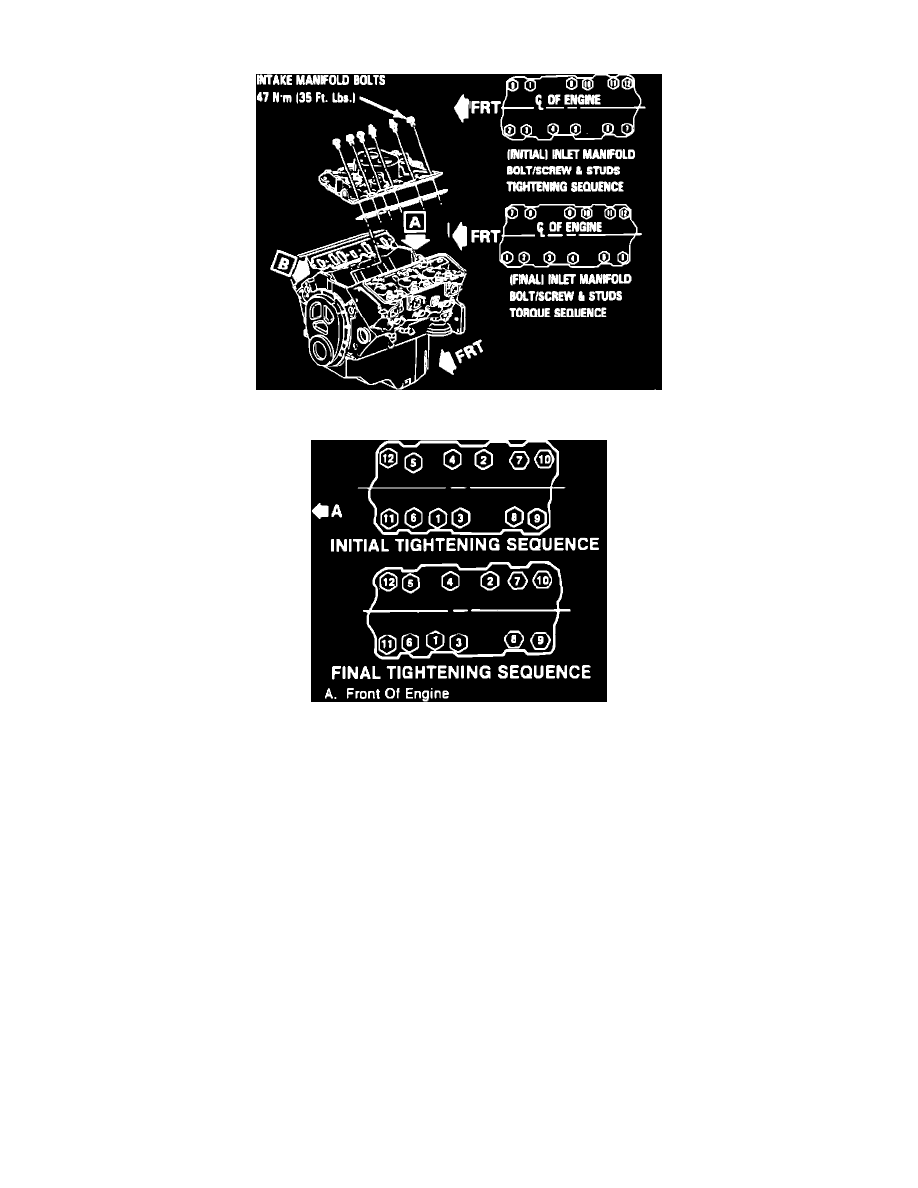
Fig. 9 Intake manifold tightening sequence
Fig. 10 Intake manifold tightening sequence
1.
Disconnect battery ground cable.
2.
Remove necessary access covers.
3.
Remove air cleaner and if equipped, the heat stove tube.
4.
Drain cooling system.
5.
Remove distributor cap and wires, then disconnect ESC connector, if applicable.
6.
Remove distributor.
7.
Disconnect detent and accelerator cables.
8.
Disconnect cruise control transducer, cable and bracket, if equipped.
9.
On 1987 R and V models, remove rear A/C compressor brace. On 1987 G models and all 1988-92 models, remove A/C compressor and position
aside.
10.
On all models, remove A/C idler pulley, if equipped.
11.
Remove alternator brace, then on carbureted models, disconnect fuel line from carburetor.
12.
Disconnect all vacuum hoses and electrical connections from the manifold and carburetor or TBI unit.
13.
Remove power brake vacuum pipe, and the upper radiator hose.
14.
Remove heater pipe, coil wires and the EGR vacuum line.
15.
Remove right hand sensors with bracket, and the right hand wiring harness.
16.
Remove transmission dipstick tube, if equipped.
17.
Remove intake manifold attaching bolts, then the intake manifold and gasket.
18.
Reverse procedure to install, using new gaskets and seals. Coat front and rear ridges of cylinder case with a 3/16 inch bead of RTV sealant. Extend
bead 1/2 inch up each cylinder head to retain side gaskets, then seal around all water passages. Tighten manifold bolts to specification in sequence
shown in Figs. 9 and 10.