
G 2500 3/4 Ton Van V6-262 4.3L VIN Z (1992)
Testing for Short with Self-Powered Test Light or Ohmmeter
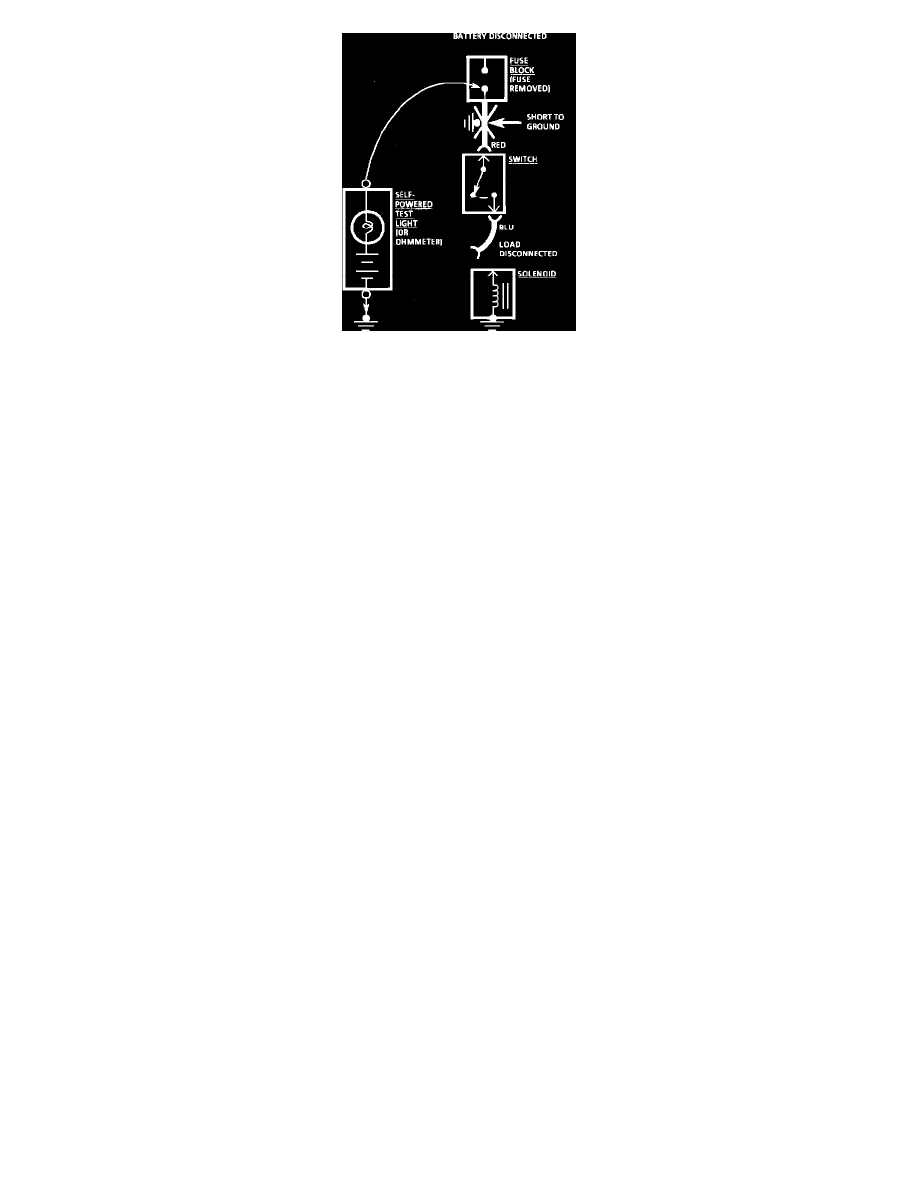
With a Self-Powered Test Light or Ohmmeter
1. Remove the blown fuse and disconnect the Battery and load.
2. Connect one lead of a self-powered test light or ohmmeter to the fuse terminal on the load side.
3. Connect the other lead to a known good ground.
4. Beginning near the Fuse Block, wiggle the harness from side to side. Continue this at convenient points (about 6 inches apart) while watching
the self-powered test light or ohmmeter.
5. When the self-powered test light glows, or the ohmmeter registers, there is a short to ground in the wiring near that point.
Fuses Powering Several Loads
1. Find the schematic under FUSE BLOCK DETAILS for the fuse that has blown.
2. Open the first connector or switch leading from the fuse to each load.
3. Replace the fuse.
^
If the fuse blows, the short is in the wiring leading to the first connector or switch. Use a test light or meter as described previously.
^
If fuse does not blow, refer to next step.
4. Close each connector or switch until the fuse blows in order to find which circuit the short is in. Connect test lamp or meter at the connector to
the suspect circuit (disconnected) rather than at the fuse terminals.
Troubleshooting Tools
TEST LIGHT/VOLTMETER
Use a test light to check for voltage. A Test Light is made up of a 12 volt light bulb, with a pair of leads attached. After grounding one lead, touch
the other lead to various points along the circuit where voltage should be present. When the bulb goes on, there is voltage at the point being tested.
A voltmeter can be used instead of a test light. While a test light shows whether or not voltage is present, a voltmeter indicates how much voltage
is present.
An increasing number of circuits include solid state control modules. One example is the Electronic Control Module (ECM). Voltages in these
circuits should be tested only with a 10-megaohm or higher impedance digital voltmeter or multimeter. Unless directed to within the diagnostics,
never use a test light on circuits that contain soled state components, since damage to these components may result.
When testing for voltage or continuity at the connection, it is not necessary to separate the two halves of the connector. Unless testing a Weather
Pack(R) connector, always probe the connector from the back. Always check both sides of the connector. An accumulation of dirt and corrosion
between contact surfaces is sometimes a cause of electrical problems.
CONNECTOR TEST ADAPTERS
A GM connector Adapter Kit (J 35616) is available for making tests and measurements at separated connectors. This kit contains an assortment of
probes which mate with many of the types of terminals you will see. Avoid using paper clips and other substitutes since they can damage terminals
and cause incorrect measurements.
SELF-POWERED TEST LIGHT
A self-powered test light can be used to check for continuity. This tool is made up of a light bulb, Battery and two leads. If the leads are touched
together, the bulb will go on. A self-powered test light is used only on an unpowered circuit. First remove the fuse which feeds the circuit you're
working on. Select two specific points along the circuit through which there should be continuity. Connect one lead of the self-powered test light
to each point. If there is continuity, the test light circuit will be completed and the bulb will go on. Never use a self-powered test light on circuits
that contain solid state components, since damage to these components may result.
OHMMETER
An ohmmeter can be used instead of a self-powered test light. The ohmmeter shows how much resistance there is between two points along a
circuit. Low resistance means good continuity. Circuits which include any solid state control modules, such as the Electronic Control Module