
G 2500 3/4 Ton Van V6-262 4.3L VIN Z (1992)
Wiper Motor: Description and Operation
Permanent Magnet Motor
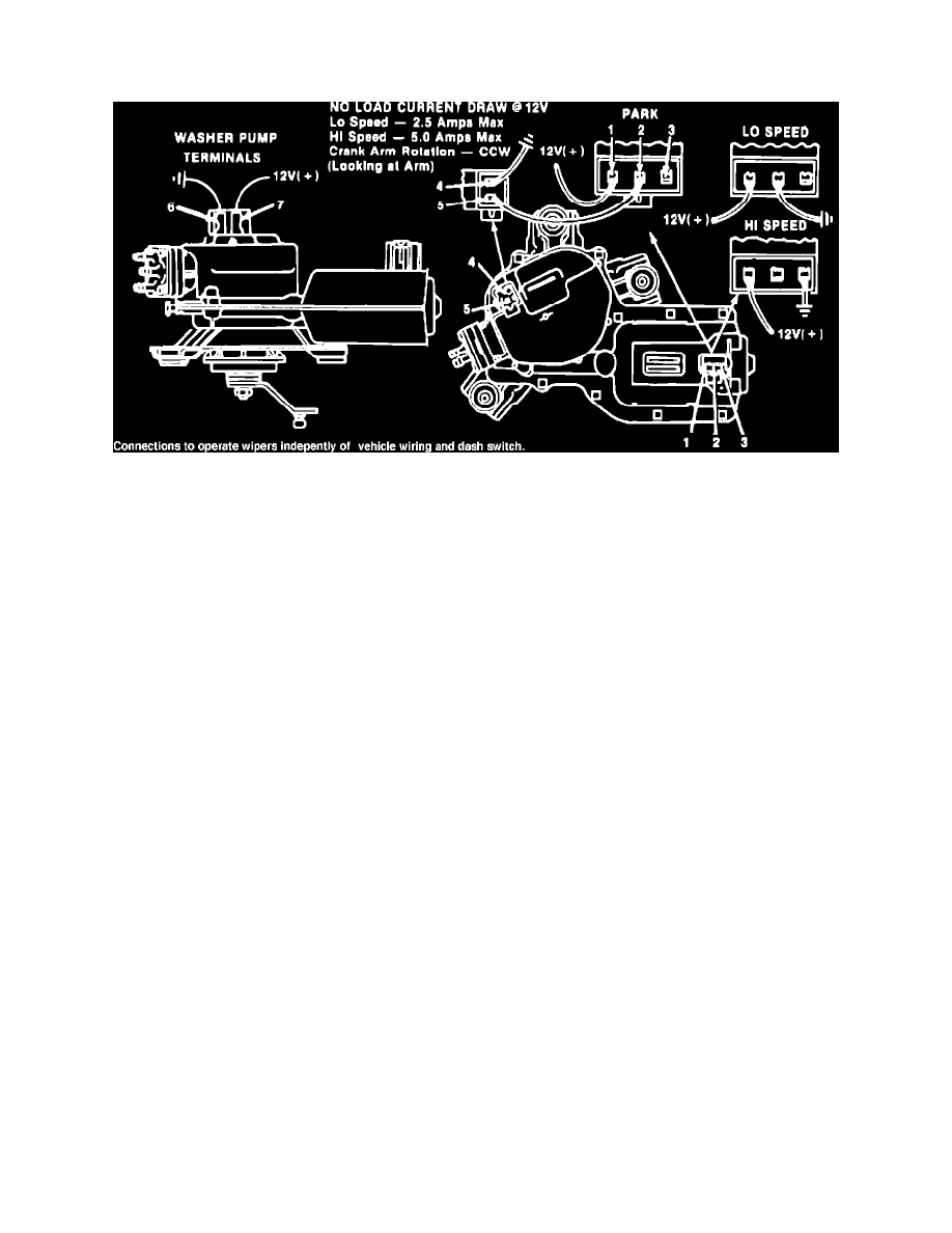
Fig. 1 Permanent magnet type windshield wiper motor
Wiper motor internal components, including permanent magnet fields, armature, brush holder, gear train and park switch, are enclosed in a two-piece
housing which is held together by ten staked extrusions. The brush holder and motor run terminals are at one end of the motor, and the gearbox and park
switch at the other end, Fig. 1. Motor operation is controlled by three brushes, common, low and high speed.
When ignition is on, battery voltage is supplied to the common brush through a fuse in the fuse block. Motor speeds are determined by completing the
low or high speed brush circuit to ground at the wiper switch. Pulse wiper operation, if equipped, is controlled by a variable resistor in the wiper switch
and by a pulse module connected between the wiper motor and switch.
Standard (Non-Pulse) Wiper Operation
When ignition is on, battery voltage is supplied to the common brush through motor terminal 1, Fig. 1. Placing wiper switch in low or high position
completes the ground circuit to motor terminal 2 (low) or 3 (high) at the switch, and the motor runs at the selected speed. When the wiper switch is
turned off, park switch terminal 5 is grounded at the wiper switch. Park switch terminal 4 is connected to the low speed terminal through the wiring
harness, and the closed park switch allows motor to continue running. When wipers reach their lowest point of travel, a cam on the output gear opens the
park switch, and the motor stops.
Pulse Wiper Operation
In addition to standard wiper system components, models with pulse wipers use a variable resistor in the wiper switch and a control module connected
between the motor and switch to provide a delay wipe mode. Current flow between the wiper motor and switch passes through the pulse control module,
and the wiper switch is grounded through the module. However, when wiper switch is in low or high position, the pulse module does not affect system
operation.
When the wiper switch is in delay position, battery voltage is applied to the control module timer through the motor low speed circuit, and the timer is
partially grounded through the variable resistor. When the timer capacitor is fully charged, the low speed circuit is completed to ground at the module,
starting the wipe cycle. As motor begins to operate, the park switch closes, the timer capacitor discharges, and the low speed circuit is grounded through
the park switch. When wipers complete their cycle, the park switch opens, the motor stops, and the timer capacitor begins to recharge.
This cycle repeats as long as the wiper switch is in delay position. Delay between wipe cycles is determined by varying resistance between the timer
capacitor and ground.