
G 2500 3/4 Ton Van V6-262 4.3L VIN Z TBI (1995)
Cruise Control Module: Diagram Information and Instructions
Abbreviation
A/C
Air Conditioning
ECM
Electronic Control Module or Engine Control Module
PCM
Powertrain Control Module
I/P
Instrument Panel
RH
Right Hand, as seen from driver's seat
LH
Left Hand
Not Used
The connector cavity has no function.
Cell References
CELL REFERENCES
General Motors vehicles often use "CELL" references in their electrical wiring diagrams. These references are used in the Original Equipment
Manual to refer to a section in the manual and not a specific diagram(s).
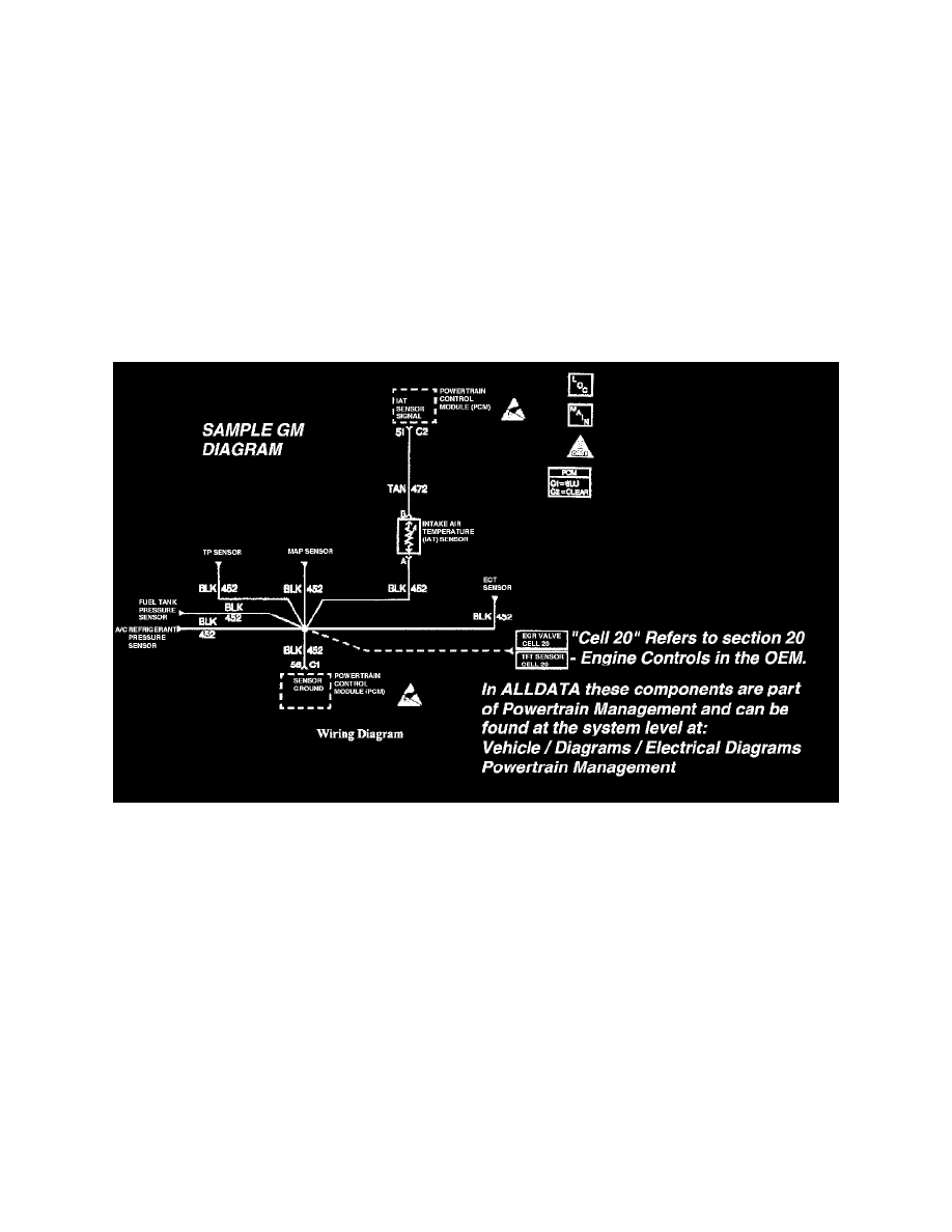
GM Sample Diagram W/ Cell Reference
For instance, in the diagram illustrated "Cell 20" is not a reference to another diagram but a reference to "Section 20" in the OE manual. In the
example, "Section 20" is the engine control section of the manual.
To navigate through these "Cell" references start at the vehicle level and go to: Diagrams / Electrical Diagrams - for a complete list of the diagrams
available for the vehicle. Choose the system you are working on and view those diagrams.
Note: If unsure of the system - try utilizing the search feature. Type a component in the search feature that belongs to the system and when the
results are displayed note the path displayed. This will show the system the component belongs in.
Electrostatic Discharge (ESD) Warnings
Many solid state electrical components, such as those found in the instrument panel and the radio, can be damaged by Electrostatic Discharge (ESD).
Some will display a label, but many will not. In order to avoid possible damage to any components, observe the following:
1. Body movement produces electrostatic charge. To discharge personal static electricity, touch ground point (metal) on vehicle. This should be done
any time you slide across seat, sit down, get up or do any walking.
2. Do not touch exposed electric terminals on components with your finger or any tools. The connector being checked might be tied into a circuit
which, in turn, could be damaged by electrostatic discharge.
3. When using a screwdriver or similar tool to disconnect a connector, never let tool come in contact with or come between exposed terminals.
4. Never jump, ground or use test equipment probes on any components or connectors unless specified in diagnosis. When using test equipment,
always connect ground lead first.