
G 2500 3/4 Ton Van V8-350 5.7L VIN K TBI (1995)
Seal Splice Sequence
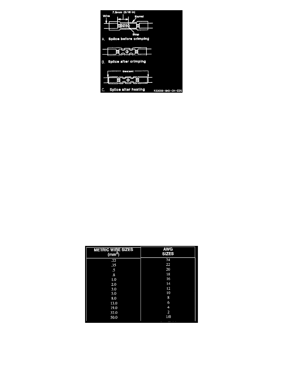
The sleeve has a stop in the middle of the barrel to prevent the wire from going further. Close the hand crimper handles slightly to hold the splice
sleeve firmly in the proper nest.
Step Five: Insert Wires into the Splice Sleeve and Crimp
Insert the wire into the splice sleeve until it hits the barrel stop, and close the handles of the J 38125-8 crimper tightly until the crimper handles
open when released. The crimper handles will not open until the proper amount of pressure is applied to the splice sleeve. Repeat steps 4 and 5 for
opposite end of the splice.
Step Six: Shrink the Insulation around the Splice
Using a heat torch, apply heat where the barrel is crimped. Gradually move the heat barrel to the open end of the tubing, shrinking the tubing
completely as the heat is moved along the insulation. A small amount of sealant will come out of the end of the tubing when sufficient shrinkage is
achieved.
Splicing Copper Wire Using Splice Clips
Splice clips are included in the J 38125 Terminal Repair Kit. The Splice Clip is a general purpose wire repair device. It may not be acceptable for
applications having special requirements such as moisture sealing.
Step One: Open the Harness
If the harness is taped, remove the tape. To avoid wire insulation damage, use a sewing "seam ripper" to cut open the harness (available from
sewing supply stores). If the harness has a black plastic conduit, simply pull out the desired wire.
Step Two: Cut the Wire
Begin by cutting as little wire off the harness as possible. You may need the extra length of wire later if you decide to cut more wire off to change
the location of a splice. You may have to adjust splice locations to make certain that each splice is at least 40 mm (1-1/2 in) away from other
splices, harness branches, or connectors. This will help prevent moisture from bridging adjacent splices and causing damage.
Wire Size Conversion Table
Step Three: Strip the Insulation
The table shows the commercial (AWG) wire sizes that can be used to replace each of the metric wire sizes. Each AWG size shown is equal to or
larger than the equivalent metric wire size.