
G 2500 3/4 Ton Van V8-350 5.7L VIN K TBI (1995)
Installing Clutch Plate & Hub Assembly
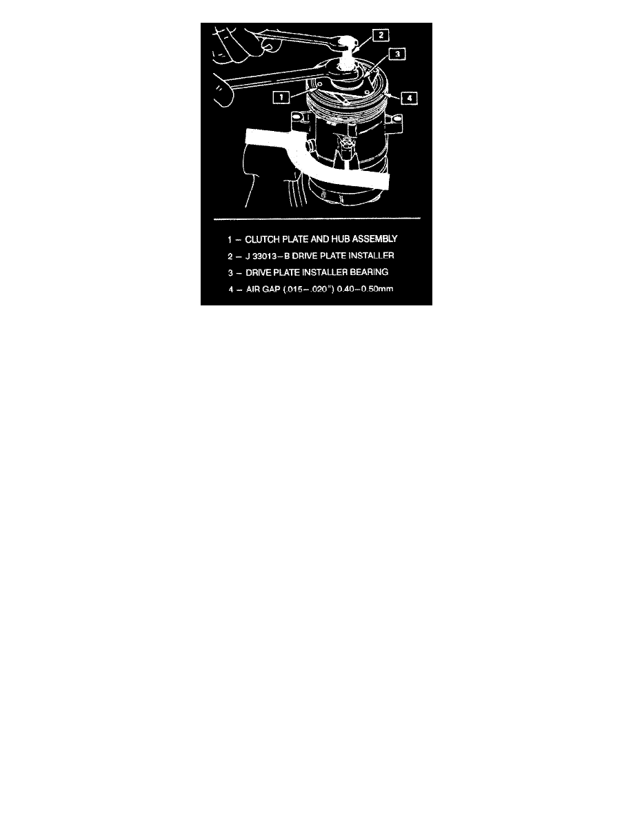
4. Remove the J 33013-B remover-installer center screw and reverse the body direction on the center screw as shown in the illustration.
5. Install the clutch plate and hub installer J 33013-B with bearing as shown in the illustration.
The body of the J 33013-B installer should be backed off sufficiently to allow the center screw to be threaded onto the end of the compressor shaft.
6. Hold the center screw with a wrench. Tighten the hex portion of the installer J 33013-B body to press the hub onto the shaft. Tighten the body
several turns, remove the installer and check to see that the shaft key is still in place in the keyway before installing the clutch plate and hub
assembly to its final position. The air gap between frictional surfaces of the clutch plate and clutch rotor should be 0.40-0.50mm (0.015-0.020").
^
If the center screw is threaded fully onto the end of the compressor shaft, or if the body of the installer is held and the center screw is rotated,
the key will assume the position as shown in Figure 6 and will break the clutch hub.
7. Remove installer J 33013-B, check for proper positioning of the shaft key (even or slightly above the clutch hub). Install the shaft nut. Hold the
clutch plate and hub assembly with clutch hub holding tool J 33027-A and using shaft nut socket J 33022, tighten the nut against the crankshaft
shoulder to 16.5 N.m (12 lbs.ft.) torque, using a 17.5 N.m (12.5 lbs.ft.) torque wrench.
8. Spin the pulley rotor by hand to see that the rotor is not rubbing the clutch drive plate.
Clutch Rotor and/or Bearing
Remove or Disconnect
1. Remove the clutch plate and hub assembly as described previously.