
G 2500 3/4 Ton Van V8-350 5.7L VIN K TBI (1995)
Voltage Check
1. Connect one lead of a test light to a known good ground. If you are using a voltmeter, be sure it is the voltmeter's negative lead that you have
connected to ground.
2. Connect the other lead of the test lamp or voltmeter to a selected test point (connector or terminal).
3. If the test lamp glows, there is voltage present. If you are using a voltmeter, note the voltage reading. It should be within one volt of measured
battery voltage. A loss of more than one volt indicates a problem.
Continuity
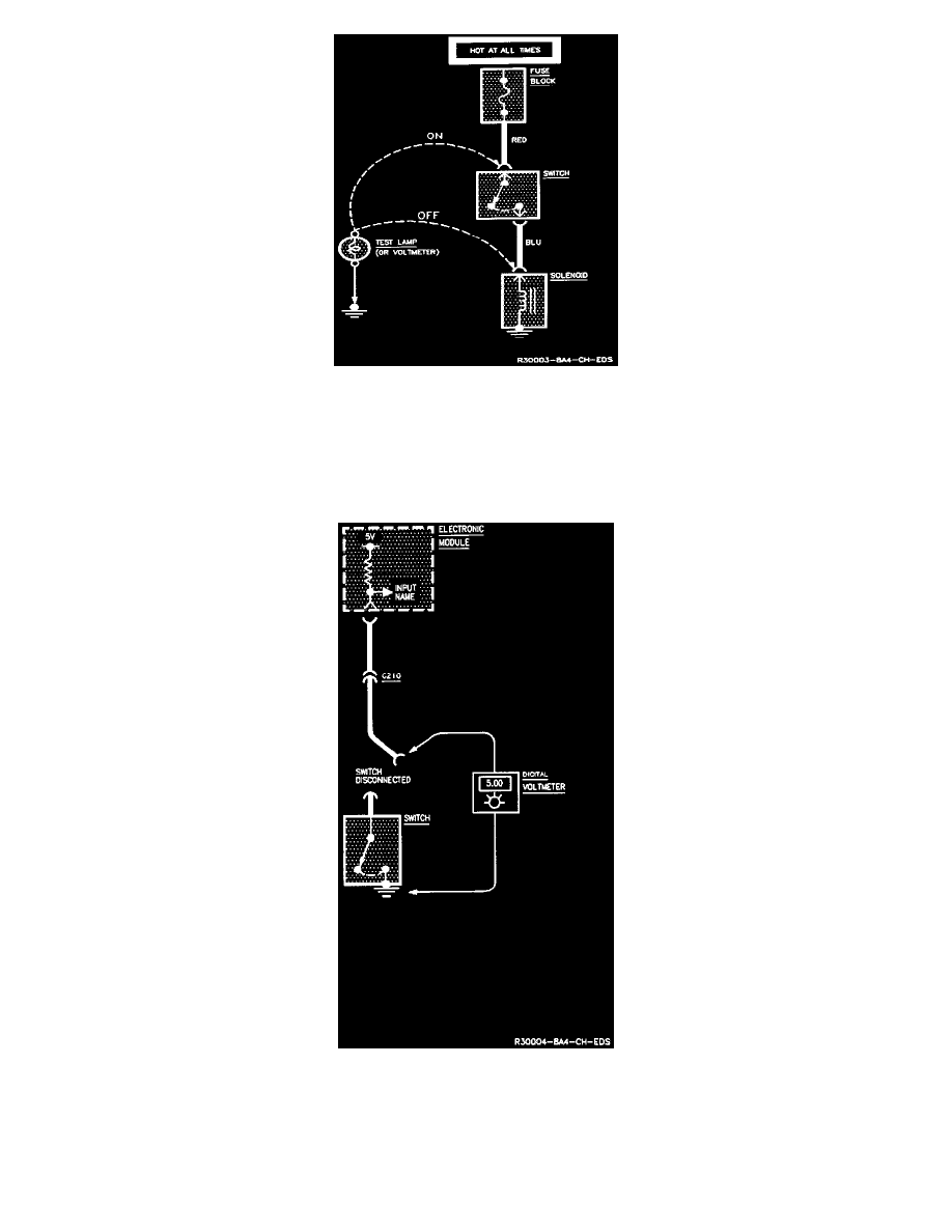
4. A quick test of wire continuity can often be made using voltages of solid state modules.
If the continuity of the wire is good, 5 volts will be found at the switch connector. This test can be performed only with a Digital Voltmeter. Analog
meters or Test Lamps will not work.