
G 2500 3/4 Ton Van V8-6.5L DSL Turbo VIN F (1996)
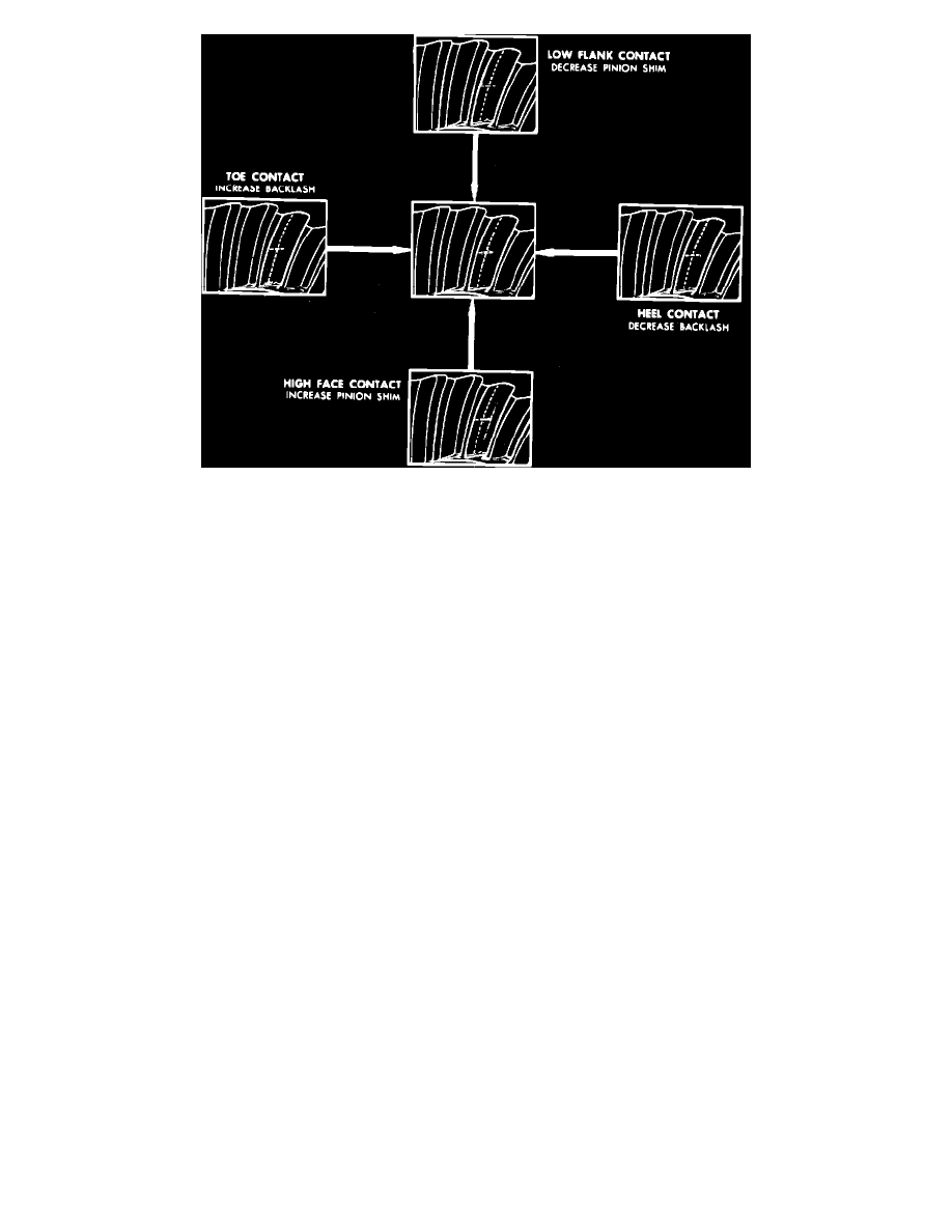
Fig. 12 Gear Tooth Contact Inspection
13.
Examine gear tooth contact pattern, referring to
Fig. 12, and correct assembly adjustments as needed.
14.
When proper gear tooth contact pattern has been established, install axle shafts, then
torque pinion shaft lock screw to 20 ft. lbs.
15.
Install rear cover and new gasket and fill axle with specified lubricant.
Cleaning & Inspection
1.
Clean components in suitable solvent and blow dry with compressed air, noting the following:
a. Do not use brush when cleaning bearings.
b. Do not ``spin dry'' bearings as bearings will be damaged.
c. Lightly lubricate components after cleaning to retard corrosion.
d. Keep all components in order to ensure proper assembly.
2.
Inspect gears for cracks, chipped or broken teeth, wear and scoring. Replace gears that are damaged or excessively worn.
Ring gear and pinion
must be replaced as an assembly.
3.
Inspect differential case for cracks, damage, distortion, worn side gear bores and scored bearing surfaces, and replace as needed.
4.
Inspect housing for scored bearing mount surfaces, cracks and distortion, and replace as needed. Ensure that housing is clean and free from foreign
material.
5.
Inspect bearing rollers and races for pitting, scoring, overheating and damage.
6.
Mate each bearing with race and check operation.
7.
Replace any bearing assembly that is damaged, excessively worn, or that fails to operate smoothly.
8.
Mount differential case along with side bearings and ring gear in housing, adjust side bearings to zero preload and check ring gear runout with dial
indicator bearing against machined edge of gear.
9.
If ring gear runout exceeds .003 inch and gear cannot be repositioned to reduce runout, replace ring gear and/or differential case.
Corporate - Standard
1.
If case side bearings are to be replaced, remove bearings using suitable puller, ensuring that puller is properly seated in recesses in case.
2.
Remove ring gear retaining bolts, then tap gear from case using suitable drift. Do not pry gear from case as machined surfaces will be damaged.
3.
Remove side gears and thrust washers from case noting position for assembly.
4.
Inspect components. Refer to
Cleaning and Inspection. See: 9 1/2 Inch Ring Gear/Cleaning & Inspection
Coat all components with specified axle lubricant prior to assembly. If components are to be reused, they must be installed in original
position.