
K 1500 Truck 4WD V8-350 5.7L (1986)
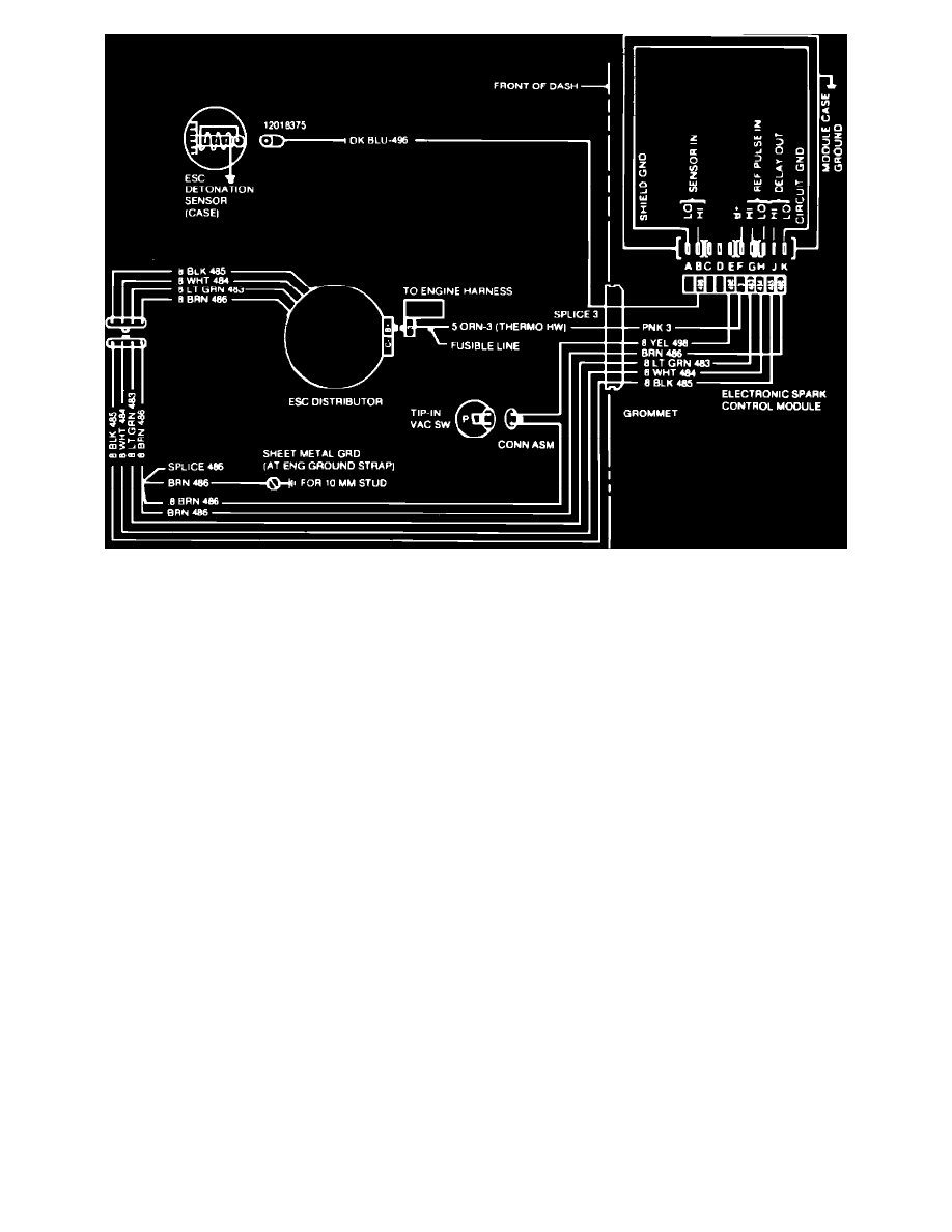
Fig. 7 ESC system wiring schematic. 1984-86 models w/auto. trans.
1984-86 MODELS
Engine Cranks But Will Not Start
1.
Check for spark at at the ends of at least 2 spark plug wires using tester ST-125 or equivalent. If spark is observed, malfunction is not in ignition
system.
2.
If no spark is observed, disconnect 4 pin connector to distributor, connect jumper wire between pins A and C on distributor side of connector,
Figs. 5, 6 and 7, and attempt to start engine. If engine starts, proceed to step 3. If engine does not start, proceed as follows:
a. Remove jumper wire and reconnect 4 pin connector to distributor. Turn on ignition and measure voltage at pins F and K of controller 10 pin
connector. If voltage is less than 11.6 volts, check feed circuit and repair as needed.
b. Set voltmeter on 2 volt scale and measure voltage between pins J and K of 10 pin connector while cranking engine. If reading is .75 volts or
greater, ESC system is satisfactory.
c. Set voltmeter on 2 volt scale and measure voltage between pins G and H of 10 pin connector while cranking engine. If reading is .20 volt or
greater, controller is defective. If reading is less than .20 volt, pole piece is defective.
3.
Stop engine and remove jumper wire from distributor.
4.
Connect suitable high resistance test lamp between distributor TACH terminal and ground, then turn on ignition. If test lamp lights, proceed to step
6.
5.
If lamp does not light at TACH terminal, connect lamp between BAT terminal and ground and turn on ignition. If lamp does not light, repair feed
circuit to ignition.
6.
Crank engine with test lamp connected between distributor TACH terminal and ground. If test lamp flickers, system is satisfactory.
7.
If test lamp does not flicker as engine is cranked, connect lamp between BAT terminal and pin A on distributor side of 4 pin ESC connector, then
tap on coil. If coil makes a clicking noise when tapped, pole piece is defective.
8.
If coil does not click, remove distributor cap an disconnect and reconnect pole piece electrical connector. If coil still does not click when tapped,
ignition module is defective.
Poor Engine Performance
1.
Disconnect distributor 4 pin connector, connect pins A and C on distributor side of connector with jumper wire, and road test vehicle.
2.
If engine performance is still poor, cause is not in ESC system. If proper engine performance is restored by disconnecting ESC controller from
distributor, remove jumper wire, reconnect 4 pin connector and proceed to next step.
3.
Disconnect 10 pin connector from ESC controller, inspect terminals for proper contact, shots and opens, repair as needed, then recheck system
operation.
4.
If problem persists, disconnect 10 pin connector and measure resistance between pins B and K in connector. Reading should be 98-99 Kohms.