
K 1500 Truck 4WD V8-4.8L VIN V (1999)
ST Does Not Communicate With Instrument Cluster (Part 2 Of 2)
CIRCUIT DESCRIPTION
For a full view of the system schematic, refer to Data Link Connector (DLC) Schematics.
Modules connected to the class 2 serial data link monitor the link for serial data communications during normal vehicle operation. Operating
information and commands are exchanged among the modules. When a module receives a message for a critical operating parameter, the module
records the identification number of the module which sent the message for State of Health (Node Alive messages). A critical operating parameter
is one which, when not received, requires that the module use a default value for that parameter. Once an identification number is learned by a
module, the module will monitor for that module's Node Alive message. Each module on the class 2 serial data link which is powered and
performing functions that require detection of communications malfunction is required to send a Node Alive message every 2 seconds. When no
message is detected from a learned identification number for 5 seconds, a DTC U1 xxx (where xxx is equal to the 3 digit identification number) is
set.
CONDITIONS FOR SETTING THE DTC
^
Voltage supplied to the module is in the normal operating voltage range (approximately 9-16 volts).
^
DTC 1301 is not current.
^
A message from a learned identification number has not been detected for the past 5 seconds.
CONDITIONS FOR CLEARING THE DTC
^
A current DTC U1 xxx (where xxx is equal to the 3 digit identification number) will clear when a Node Alive message from the failed
identification number is detected on the class 2 serial data link or at the end of the current ignition cycle.
^
A history DTC U1 xxx will clear upon receipt of a scan tool Clear DTCs command.
DIAGNOSTIC AIDS
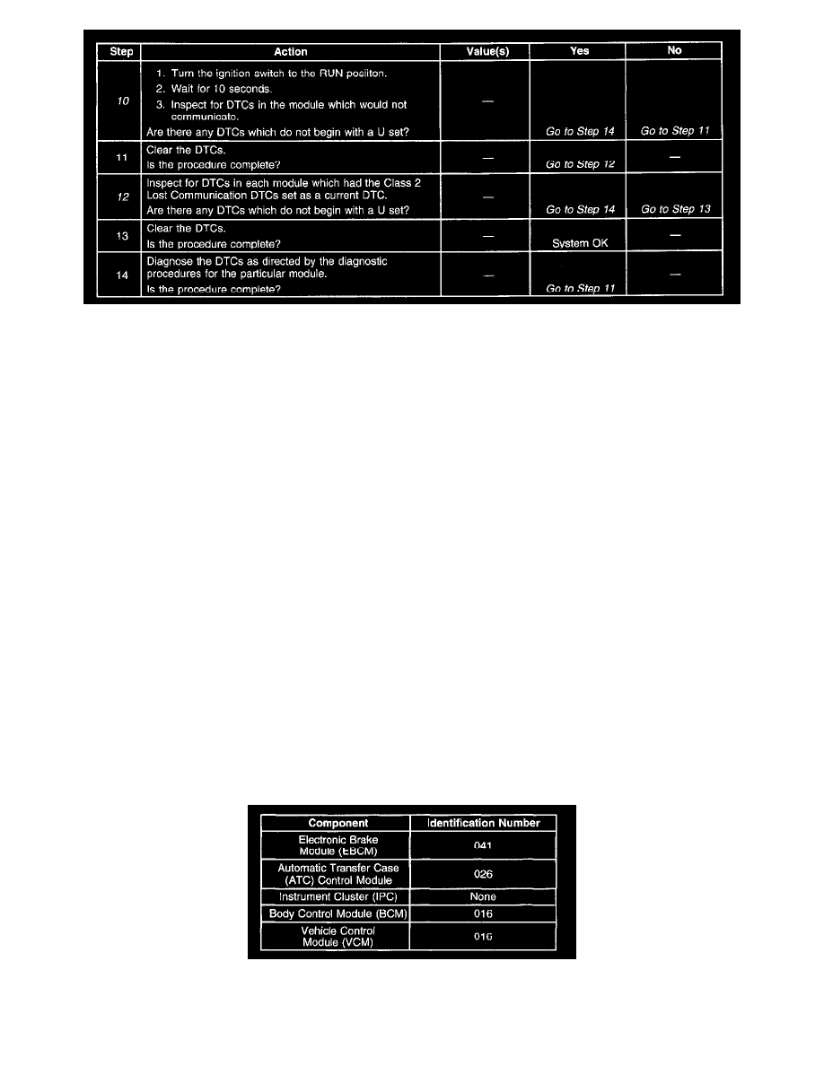
The control module identification number list provides a method for determining which module is not communicating. The diagnostic procedure
assumes that all modules are powered. A module with an internal class 2 circuit malfunction or which loses power during the current ignition cycle
would have a Lost Communication DTC set by the other modules.
Use the control module identification number in order to determine which module is not communicating and the Lost Communication with XXX
diagnostic table in order to diagnose the malfunction. The control module identification numbers are as follows:
ST Does Not Communicate With Instrument Cluster
The EBCM may set Class 2 Lost Communication DTCs when the BCM or the Powertrain Control Module (PCM/VCM) is being reprogrammed.