
K 1500 Truck 4WD V8-4.8L VIN V (1999)
(Part 3 Of 3)
TYPICAL SCAN TOOL DATA VALUES
Use the Typical Scan Tool Data Values listed in this section for comparison after the BCM Diagnostic System Check and finding the on board
diagnostics are functioning properly with no diagnostic trouble codes displayed. The Typical Scan Tool Data Values are an average of displayed
values recorded from normally operating vehicles and are intended to represent what a normally functioning system would display. The values you
get may vary due to a low battery charge or other reasons. But they should be very close.
NOTE: Do not use a scan tool that displays faulty data. Report the scan tool problem to the manufacturer. Use of a faulty scan tool can result in
misdiagnosis and unnecessary parts replacement.
Scan Tool Operation
DATA DISPLAY
The scan tool displays the Body Control Module (BCM) data. This information assists in determining whether the BCM is operating properly.
This information also assists in determining whether the BCM is sending or receiving the proper data to and from a particular system. The BCM
uses the data received from other systems in order to carry out some functions. Therefore, if the BCM receives the incorrect data from another
system, the BCM may function improperly. Use the scan tool in order to review the data from the systems that interact with the BCM.
DISPLAYED INPUT STATUS
The scan tool displays the BCM input status. Select the BCM input status display in order to display the data. Displaying the data determines it the
switched inputs can be properly interpreted. The display also indicates if the input has changed states. For example, when a door is closed, the scan
tool displays the input status of the mini wedge (door jamb) switch as INACTIVE. When the door is open, the scan tool reads ACTIVE. Use this
kind of information when diagnosing a malfunction associated with a particular BCM input or an input that is shared with another system.
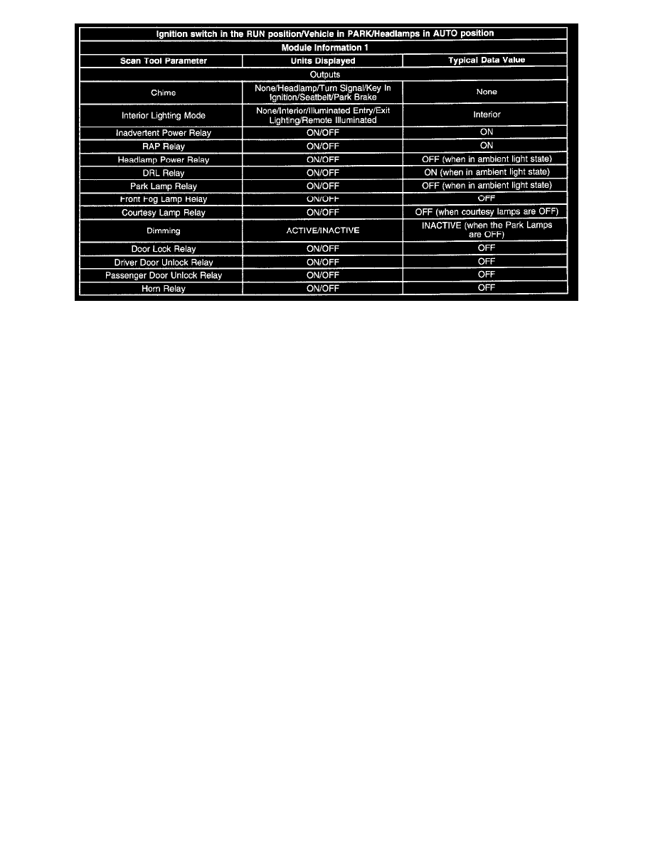
OUTPUTS
The scan tool displays the BCM output status. Select the BCM output status display in order to display the data. The data determines if the
switched outputs can be properly interpreted. The display also indicates it the outputs have changed states. For example, when the Daytime
Running Lamps (DRL) are turned on, the scan tool displays the output status of the DRL relay as ON. When the DRL relay is off, the scan tool
reads OFF. Use this kind of information when diagnosing a malfunction associated with a particular BCM output.
SECURITY DATA
The scan tool monitors the security data status. Select the security data status display in order to display the data. The data determines if the
switched inputs can be properly interpreted. The data indicates when, and if, the input has changed states.
SPECIAL FUNCTIONS
There are 2 features under special function.
OUTPUT CONTROLS
Use a scan tool in order to cycle the BCM output functions. When the BCM output cycling is selected, the scan tool can command the BCM to
cycle an output. Use this feature in order to determine if the BCM is able to cycle an output regardless of the inputs or any specific program
instructions. Once you select a test, the scan tool will command the BCM to energize the selected output. The scan tool then displays the status of
the selected output. The displayed information represents only what the BCM commanded, not what action was actually taken. Verify that the