
K 1500 Truck 4WD V8-4.8L VIN V (1999)
Brake Lamp Relay: Diagram Information and Instructions
Electrical Schematics
IMPORTANT: The schematic does not represent the components and wiring as they physically appear on the vehicle. For example, a 4-foot length of
wire is treated no differently in a schematic from one which is only a few inches long.
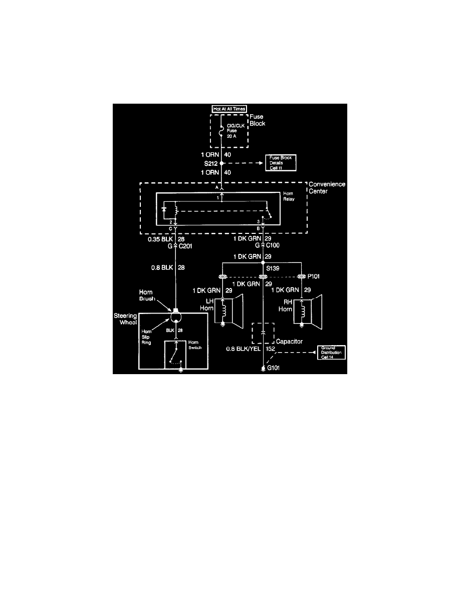
When diagnosing a horn problem use the service information located in the Horns service category. The following schematic is a typical example of a
schematic with its supporting text.
Wiring System
The wiring schematic is the cornerstone of electrical diagnosis. Schematics break the entire electrical system into individual circuits, showing the
electrical current paths when a circuit is operating properly. Wiring which is not part of the circuit of interest is referenced to another page where the
circuit is shown complete. Schematics use a top (power) to bottom (ground) sequence to present electrical information.
Component Location Views
Component location views are line illustrations that indicate all of the vehicle's electrical components within each electrical system.