
K 1500 Truck 4WD V8-5.3L VIN T (2000)
Control Assembly: Description and Operation
HVAC System - Manual
HVAC Air Delivery/Temperature Control Circuit Description
The HVAC air delivery electrical system consists of a control module, blower switch, mode and temperature potentiometers & (motors), recirculating
outside air control push button, temperature, mode and recirculating motors that operate their respective actuators and doors.
The mode, recirculating and temperature door motors are powered by ignition 3 voltage when the ignition switch is in the RUN position. The ground
path is provided by the body wiring harness junction block to ground located in the left hand upper plenum area. The HVAC control module is powered
by ignition 3 voltage from the HVAC fuse located in the fuse block when the ignition switch is in the RUN position. Grounding for the module is
through the same circuit utilized for the door motors.
The recirculating door motor is controlled by a signal from the HVAC control module via recirculation actuator control when the push button is activated
on the control head. Also, the recirculation door motor can be controlled by the PCM/VCM which monitors the automatic recirculation switch activity
(located at the bottom right hand side of the air conditioning (A/C) condenser) and will signal the door motor to the recirculating mode when the switch
closes due to high refrigerant pressure. This will allow cooler air from inside the vehicle to flow over the A/C evaporator thus cooling the refrigerant
temperature.
Pressing the recirculation button activates several different modes in the HVAC system. An A/C request is made anytime the recirculation button is
selected. Recirculation is only available in vent or bi-level modes only. Vent and bi-level are the first 8 of 17 detents on the mode switch. Recirculation
can be selected with the blower motor in either the ON or OFF position.
The mode and temperature door motors are positioned in proportion to the variable voltage signal received from the HVAC control module. Adjusting
the temperature dial (potentiometer) in the control head provided a variable voltage to the door motor via temp actuator control. There is a constant 5
volt reference sent to both motors via 5 volt reference from the control module. The module uses this reference voltage to accurately determine the door
motor position through a feed back temp actuator signal which also varies from 0-5 Volts (Pickup). The Utilities with rear A/C and Heat use Mode and
Temperature door motors that operate from the front or rear control (non-sunroof vehicles) using a 0-12 Volts signal.
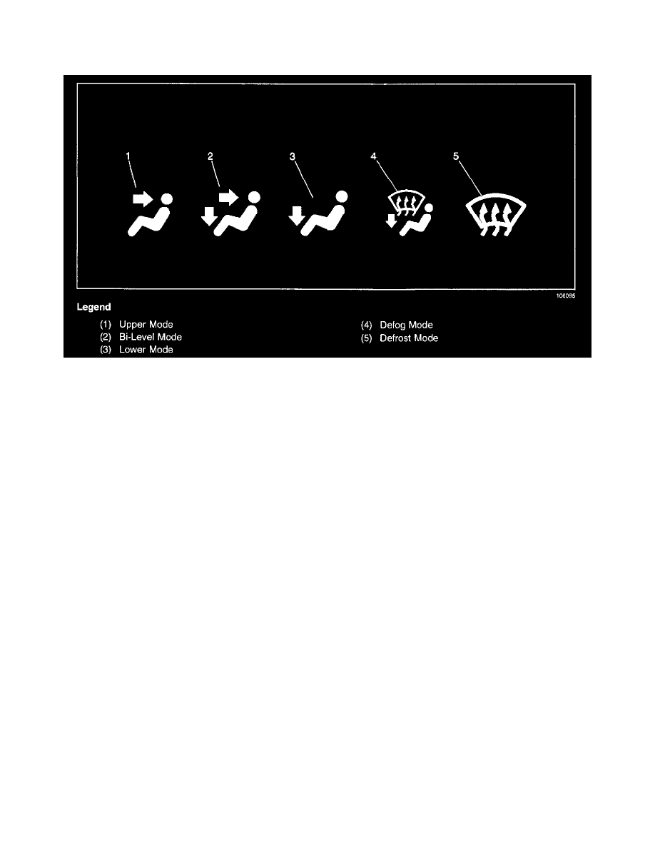
The mode switch will allow A/C to be directed out of any discharge vents. Even with the HVAC system off, the mode switch can still direct the ram air
out of any discharge vents.
HVAC Blower Controls Circuit Description
HVAC BLOWER CONTROLS CIRCUIT DESCRIPTION
Battery voltage is supplied to the blower motor resistor relay assembly connector at all times. When the ignition switch is OFF or the blower switch is in
any position except HI, no voltage is applied to the relay coil via blower high speed and the relay remains de-energized.
With the blower switch in HI, the blower resistors are bypassed and voltage is supplied to the coil side of the permanently grounded relay. This closes
the contacts and supplies full battery voltage from the engine wiring harness junction block to the blower motor which will operate at the highest speed.
When the blower switch is in LO to any MEDIUM speed, voltage is reduced through the appropriate resistors which will limit the blower speed