
K 1500 Truck 4WD V8-5.3L VIN T (2000)
^
Automatic Transfer Case (ATC)
^
Inflatable Restraint Sensing and Diagnostic Module (SDM)
^
Instrument Cluster (IPC)
^
Body Control Module (BCM)
^
Electronic Brake Control Module (EBCM)
^
Suspension Control Module (SCM)
^
HVAC Control Module
3. The following DTCs may be retrieved with a history status:
^
U1300
^
U1301
These DTCs are not the cause of the present condition.
4. A State of Health DTC with a history status may be present along with a U1000 or U1255 having a current status. This indicates that the
malfunction occurred when the ignition was ON.
5. Data link connector terminals 2 and 5 provide the connection to the class 2 serial data circuit and the signal ground circuit respectively.
7. A poor connection at terminal A would cause this condition but will not set a DTC.
8. An open in the class 2 serial data circuit between the DLC and splice pack SP 205 will prevent the scan tool from communicating with any
module. This condition will not set a DTC.
9. The class 2 serial data circuit is shorted to voltage or ground. The condition may be due to the wiring or due to a malfunction in one of the
modules. When testing the wiring for a short, make sure there is not a module connected to the wire being tested. This test isolates the BCM class
2 serial data circuit.
11. This test isolates the PCM/VCM class 2 serial data circuit.
13. This test isolates the ATC class 2 serial data circuit.
15. This test isolates the EBCM class 2 serial data circuit.
17. This test isolates the SDM class 2 serial data circuit.
19. This test isolates the IPC class 2 serial data circuit.
32. If there are no current DTCs that begin with a U, the communication malfunction has been repaired.
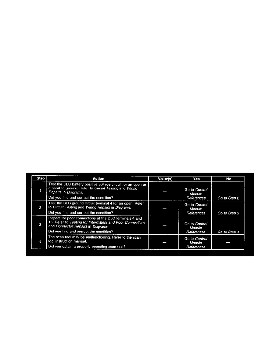
Scan Tool Does Not Power Up
Diagnostic Chart
CIRCUIT DESCRIPTION
The data link connector (DLC) provides operating power for the scan tool at terminal 16 (battery positive voltage) and at terminal 4 (ground). The
DLC provides the class 2 serial data signal at terminal 2 and signal ground at terminal 5. The scan tool will power up with the ignition OFF.
TEST DESCRIPTION
Step number(s) below refer to the same step number(s) in the Diagnostic Table
1. The CIGAR fuse supplies power to the DLC terminal 16.
4. The DLC battery positive voltage and ground circuits are functioning properly. The malfunction must be due to the scan tool.