
K 1500 Truck 4WD V8-5.3L VIN T (2000)
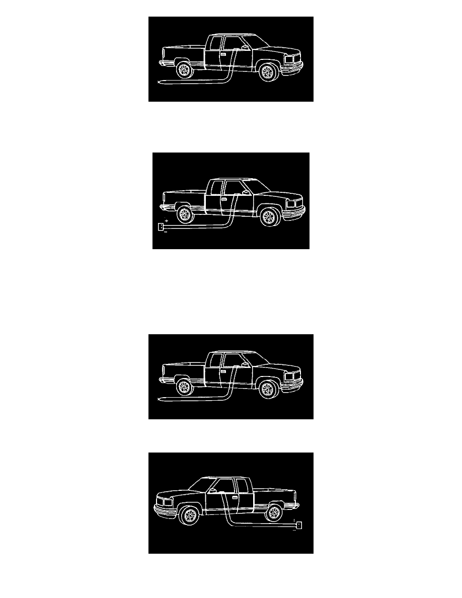
53. Route the deployment harness out of the passenger side of the vehicle.
54. Stretch the two driver side harnesses to full length.
55. Stretch the two passenger side harnesses to full length.
56. Completely cover the windshield and front door window openings with a drop cloth.
57. Place a power source, 12 V minimum/2 A minimum (i.e., a vehicle battery) near the shorted end of the harnesses.
58. Separate the two ends of the inflatable restraint IP module deployment harness wires.
59. Connect the inflatable restraint IP module deployment harness wires to the power source in order to deploy the inflatable restraint IP module.
60. Disconnect the inflatable restraint IP module deployment harness wires from the power source.
61. Separate the two ends of the passenger inflatable restraint side impact sensor inflator module deployment harness wires.
62. Connect the inflatable restraint side impact inflator module deployment harness wires to the power source in order to deploy the inflatable restraint
side impact inflator module.
63. Disconnect the inflatable restraint side impact inflator module deployment harness wires from the power source.
64. Twist together one end of each wire of IP inflatable restraint module on the passenger side deployment harness in order to short the wires.
65. Twist together one end of each wire of side air bag module on the passenger side deployment harness in order to short the wires.
66. Move the power source, 12 V minimum/2 A minimum (i.e., a vehicle battery) near the shorted end of the harnesses to driver side.
67. Separate the two ends of the inflatable restraint steering wheel module deployment harness wires.