
K 1500 Truck 4WD V8-5.7L VIN R (1997)
Camshaft: Testing and Inspection
Lobe Lift
-
Tools Required
-
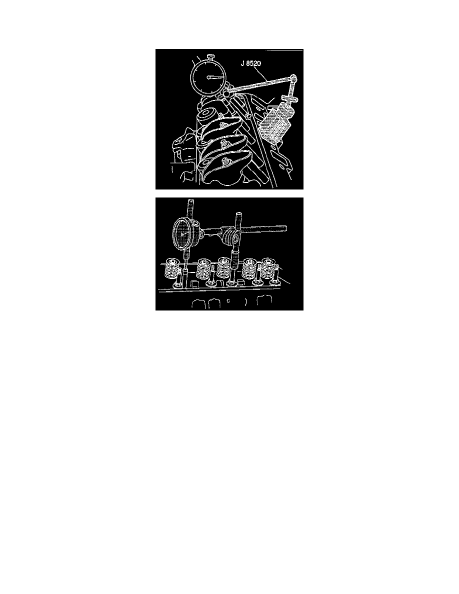
J 8520 Camshaft Lobe Lift Indicator
1. Remove the valve rocker arm.
2. Position the dial indicator (part of the J 8520) so the plunger rests on the pushrod end, as shown. Make sure the pushrod is in the valve lifter
socket.
3. Rotate the crankshaft slowly in the direction of normal rotation until the valve lifter is on the heel of the cam lobe. At this point, the pushrod will
be in its lowest position.
NOTE: Whenever the engine is cranked by the starter, disconnect the distributor or coil primary leads.
4. Set the dial indicator on zero, then rotate the crankshaft slowly until the pushrod is in the fully raised position.
5. Compare the total lift recorded from the dial indicator with specifications.
-
Intake: 6.97-7.07 mm (0.274-0.278 inch).
-
Exhaust: 7.20-7.30 mm (0.283-0.287 inch).
6. If the camshaft readings for all lobes are within specifications, remove the dial indicator assembly.
7. Install the valve rocker arm.
8. Adjust the valves.