
K 1500 Truck 4WD V8-6.5L DSL Turbo VIN S (1999)
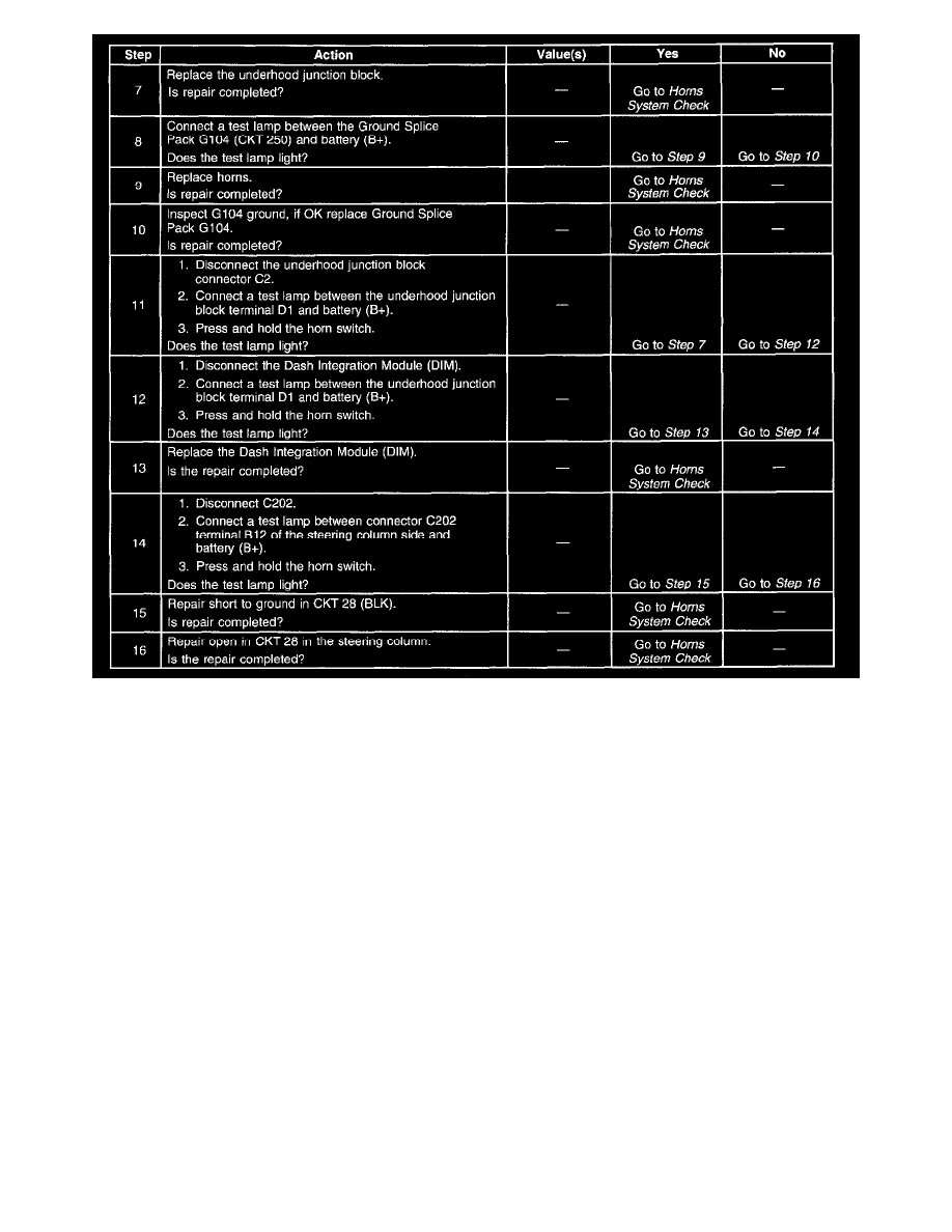
Horns Inoperative (Part 2 Of 2)
Diagnostic tables provide a procedure that will help you locate the condition in a circuit that is causing a malfunction. All diagnostic procedures are
symptom based, to assist you in locating the condition as fast as possible. Diagnostic tables should exist for all possible (realistic) symptoms and
diagnostic trouble codes (DTCs).
Circuit Descriptions
The circuit description describes how the system works electrically. It details how power, ground, inputs, and outputs are supplied to the system's related
components. The circuit description also explains the communication and interaction of all components that affect the operation of the system.
Battery positive voltage is applied at all times to the horn relay terminals 85 and 30. Pressing the horn switch grounds the horn relay coil on CKT 28
(BLK). The relay coil can also be grounded on CKT 28 (BLK) by the Dash Integration Module (DIM). The horn relay applies battery positive voltage to
the horns on CKT 29 (DK GRN) when energized. The horns sound until the horn switch is released or the DIM signal is gone.
Truck Zoning