
K 1500 Truck 4WD V8-6.5L DSL Turbo VIN S (1999)
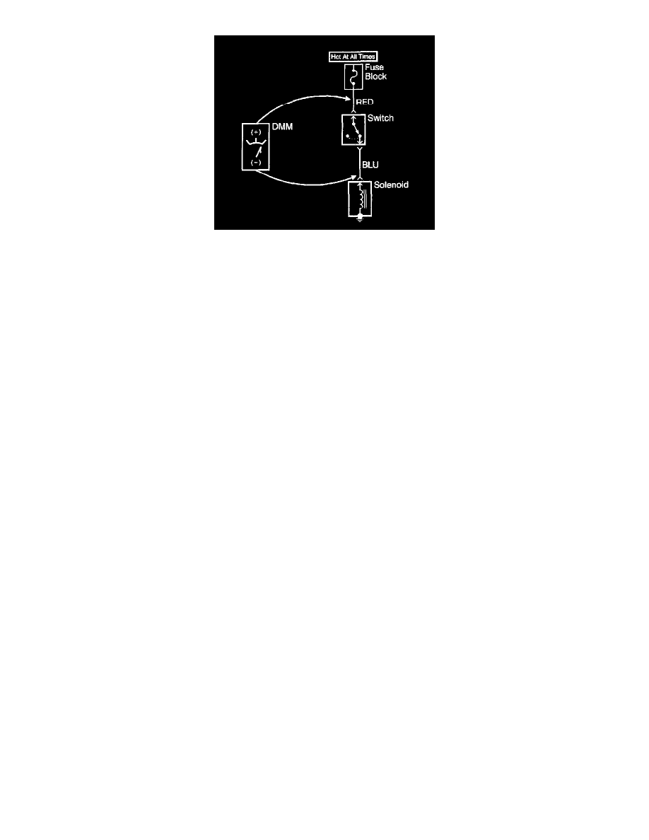
1. Set the rotary dial of the DMM to the V (DC) position.
2. Connect the positive lead of the DMM to one point of the circuit to be tested.
3. Connect the negative lead of the DMM to the other point of the circuit.
4. Operate the circuit.
5. The DMM displays the difference in voltage between the two points.
Testing For Continuity
NOTE: Refer to Test Probe Notice in Cautions and Notices.
The following procedures verify good continuity in a circuit.
With a DMM
1. Set the rotary dial of the DMM to the Ohm position.
2. Disconnect the power feed (i.e. fuse, control module) from the suspect circuit.
3. Disconnect the load.
4. Press the MIN MAX button on the DMM.
5. Connect one lead of the DMM to one end of the circuit to be tested.
6. Connect the other lead of the DMM to the other end of the circuit.
7. If the DMM displays low or no resistance and a tone is heard, the circuit has good continuity.
With a Test Lamp
IMPORTANT: Only use the test lamp procedure on low impedance power and ground circuits.
1. Remove the power feed (i.e. fuse, control module) from the suspect circuit.
2. Disconnect the load.
3. Connect one lead of the test lamp to one end of the circuit to be tested.
4. Connect the other lead of the test lamp to battery positive voltage.
5. Connect the other end of the circuit to ground.
6. If the test lamp illuminates (full intensity), then the circuit has good continuity.
Testing For Short to Ground
NOTE: Refer to Test Probe Notice in Cautions and Notices.
The following procedures test for a short to ground in a circuit.
With a DMM
1. Remove the power feed (i.e. fuse, control module) from the suspect circuit.
2. Disconnect the load.
3. Set the rotary dial of the DMM to the Ohm position.
4. Connect one lead of the DMM to one end of the circuit to be tested.
5. Connect the other lead of the DMM to a good ground.
6. If the DMM does NOT display infinite resistance (OL), there is a short to ground in the circuit.
With a Test Lamp
1. Remove the power feed (i.e. fuse, control module) from the suspect circuit.
2. Disconnect the load.
3. Connect one lead of the test lamp to battery positive voltage.