
K 1500 Truck 4WD V8-6.5L DSL Turbo VIN S (1999)
Ball Joint: Specifications
Wear Limit
-
Tools Required
-
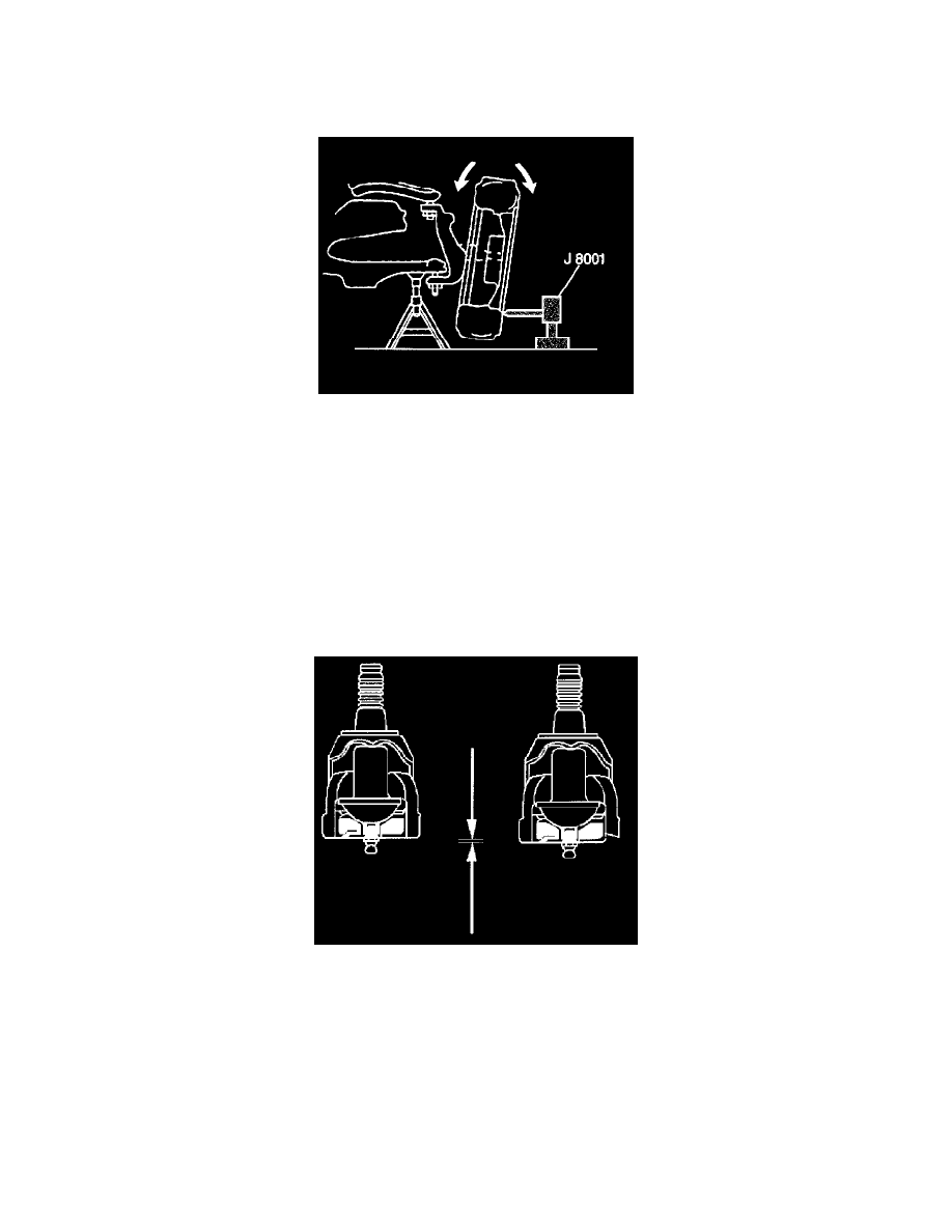
J 8001 Dial Indicator
1. Raise and support the vehicle with safety stands.
Important:
-
The vehicle must rest on a level surface.
-
The vehicle must be stable. Do not rock the vehicle on the floor stands.
-
The upper control arm bumper must not contact the frame.
2. Support the lower control arm with a floor stand or jack, as far outboard as possible, under the stabilizer bar bracket.
3. Wipe the ball joints clean. Check the seals for cuts or tears.
Important: If a seal is cut or torn, replace the ball joint.
4. Adjust the wheel bearings, RWD only.
5. Check the ball joints for horizontal looseness.
5.1. Position the dial indicator against the lowest outboard point on the wheel rim.
5.2. Rock the wheel in and out while reading the dial indicator. This shows horizontal looseness in both joints.
5.3. The indicator reading should be no more than 3.18 mm (0.125 inch). If the reading is too high, check the lower ball joints for vertical
looseness.
6. For RWD vehicles, check the lower ball joints for wear and for vertical looseness using the following procedure:
6.1. Inspect by sight the lower ball joint for wear. The position of the housing into which the grease fitting is threaded indicates wear. This round
housing projects 1.27 mm (0.050 inch) beyond the surface of the ball joint cover on a new ball joint. Under normal wear, the surface of the
ball joint housing retreats inward very slowly.
6.2. First observe, then scrape a scale, a screwdriver, or a fingernail across the cover. If the round housing is flush with or inside of the cover
surface, replace the ball joint.