
K 1500 Yukon Denali AWD V8-6.0L VIN U (2002)
Information Bus: Symptom Related Diagnostic Procedures
A Symptoms - Data Link Communications
IMPORTANT: The following steps must be completed before using the symptom tables:
1. Perform the Diagnostic System Check for the subsystem exhibiting the symptoms. The subsystem diagnostic system check will identify where to
begin diagnosis of the data link communication system.
2. Review the system operation in order to familiarize yourself with the system functions. Refer to Data Link Communications Description and
Operation.
Visual/Physical Inspection
^
Inspect for aftermarket devices that could affect the operation of the serial data communications systems. Refer to Checking Aftermarket
Accessories in Diagnostic Aids.
^
Inspect the easily accessible systems or visible system components for obvious damage or conditions that could cause the symptom.
Intermittent
Faulty electrical connections or wiring may be the cause of intermittent conditions. Refer to Testing for Intermittent and Poor Connections in
Diagnostic Aids.
Symptom List
Refer to a symptom diagnostic procedure from the following list in order to diagnose the symptom:
^
Scan Tool Does Not Power Up
^
Scan Tool Does Not Communicate with Class 2 Device
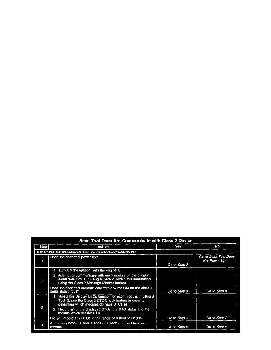
Scan Tool Does Not Communicate With Class 2 Device
CIRCUIT DESCRIPTION
Modules connected to the class 2 serial data circuit monitor for serial data communications during normal vehicle operation. Operating information
and commands are exchanged among the modules. Connecting a scan tool to the DLC allows communication with the modules for diagnostic
purposes. DTCs may be set due to this symptom and during this diagnostic procedure. Complete the diagnostic procedure in order to ensure all the
DTCs are diagnosed and cleared from memory.
DIAGNOSTIC AIDS
^
The BCM detects that the ignition is ON and sends the appropriate power mode message to the other modules. Therefore, the BCM must be
connected to the DLC for any other module to communicate with the scan tool.
^
When the class 2 serial data circuit:
^
is shorted to ground
^
is shorted to voltage
The following DTCs may set:
^
U1300
^
U1301
^
U1305
TEST DESCRIPTION