
K 1500 Yukon Denali AWD V8-6.0L VIN U (2002)
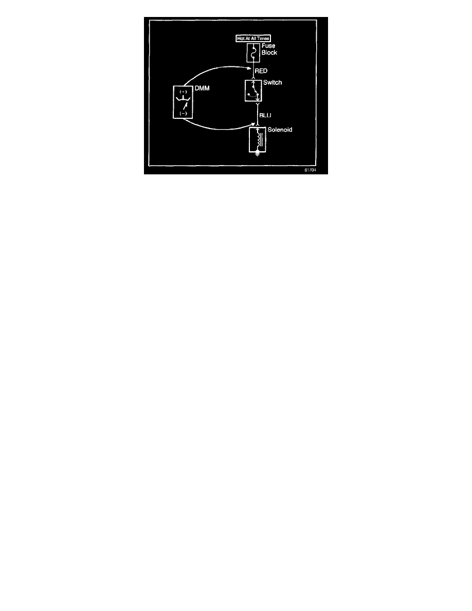
1. Set the rotary dial of the DMM to the V (DC) position.
2. Connect the positive lead of the DMM to 1 point of the circuit to be tested.
3. Connect the negative lead of the DMM to the other point of the circuit.
4. Operate the circuit.
5. The DMM displays the difference in voltage between the 2 points.
Scan Tool Snapshot Procedure
Snapshot is a recording of what a control module on the vehicle was receiving for information while the snapshot is being made. A snapshot may be used
to analyze the data during the time a vehicle condition is current. This allows you to concentrate on making the condition occur, rather than trying to
view all the data in anticipation of the fault. The snapshot contains information around a trigger point that you have determined. Only a single data list
may be recorded in each snapshot. The Scan Tool has the ability to store 2 snapshots. The ability to record 2 snapshots allows comparing hot versus cold
and good versus bad vehicle scenarios. The snapshots are stored on a 'first in, first out' basis. If a third snapshot is taken, the first snapshot stored in the
memory will be lost.
Snapshots can be 1 of 2 types:
-
Snapshot - taken from the Snapshot menu choice
-
Quick Snapshot - taken from the Data Display soft key choice, does not contain DTC information
When a snapshot is taken, it is recorded on the memory card and may contain as many as 1200 frames of information. Because the snapshot is recorded
onto the memory card, snapshots are not lost if the Scan Tool is powered down.
The snapshot replay screen has a plot soft key that can be of great value for intermittent diagnosis. The snapshot plot feature can help you to quickly
determine if a sensor is outside of its expected values by plotting three parameters at a time. The data will be displayed both graphically and numerically
showing the minimum and maximum values for all frames captured. This is helpful, especially if the fault occurs only once and does not set a DTC.
Testing For a Short To Voltage
NOTE: Refer to Test Probe Notice in Service Precautions.
The following procedure tests for a short to voltage in a circuit.
1. Set the rotary dial of the DMM to the V (DC) position.
2. Connect the positive lead of the DMM to 1 end of the circuit to be tested.
3. Connect the negative lead of the DMM to a good ground.
4. Turn ON the ignition and operate all accessories.
5. If the voltage measured is greater than 1 volt, there is a short to voltage in the circuit.
Testing for Continuity
NOTE: Refer to Test Probe Notice in Service Precautions.
The following procedures verify good continuity in a circuit.
With a DMM
1. Set the rotary dial of the DMM to the Ohm position.
2. Disconnect the power feed (i.e. fuse, control module) from the suspect circuit.
3. Disconnect the load.
4. Press the MIN MAX button on the DMM.
5. Connect one lead of the DMM to one end of the circuit to be tested.
6. Connect the other lead of the DMM to the other end of the circuit.
7. If the DMM displays low or no resistance and a tone is heard, the circuit has good continuity.