
K 1500 Yukon Denali AWD V8-6.0L VIN U (2002)
Accessory Delay Module: Initial Inspection and Diagnostic Overview
Diagnostic Starting Point - Accessory Delay Module
Begin the system diagnosis with the Diagnostic System Check Accessory Delay Module. The Diagnostic System Check will provide the following
information:
-
The identification of the control module which commands the system
-
The ability of the control module to communicate through the serial data circuit
-
The identification of any stored DTCs and their status
The use of the Diagnostic System Check will identify the correct procedure for diagnosing the system and where the procedure is located.
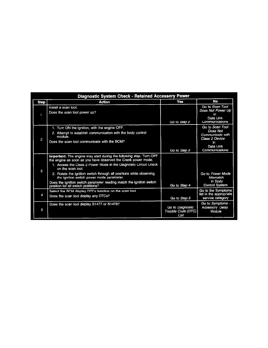
Diagnostic System Check - Accessory Delay Module
DIAGNOSTIC SYSTEM CHECK - ACCESSORY DELAY MODULE
TEST DESCRIPTION
Steps 1-5
The numbers below refer to the step numbers on the diagnostic table.
2. Lack of communication may be due to a partial malfunction of the class 2 serial data circuit or due to a total malfunction of the class 2 serial data
circuit. The specified procedure will determine the particular condition.
4. This step is checking for DTCs in the BCM.
5. This step is checking for RAP specific DTCs.